Section 4: Peering to devices outside the fabric
Setting up external connectivity
Remember the analytics-web virtual network — the one we created as Layer 2 only, without a gateway on the leaf switches? The reason for that design decision was to route all web-tier traffic through an external firewall for inspection. You now need to connect that firewall (or edge router) to the fabric.
You will model that connection in Undeploy mode, meaning the configuration is pre-staged in Apstra but will not be pushed to any switch until you change the mode to Deploy. This is how you prepare for hardware that has not physically arrived yet.
-
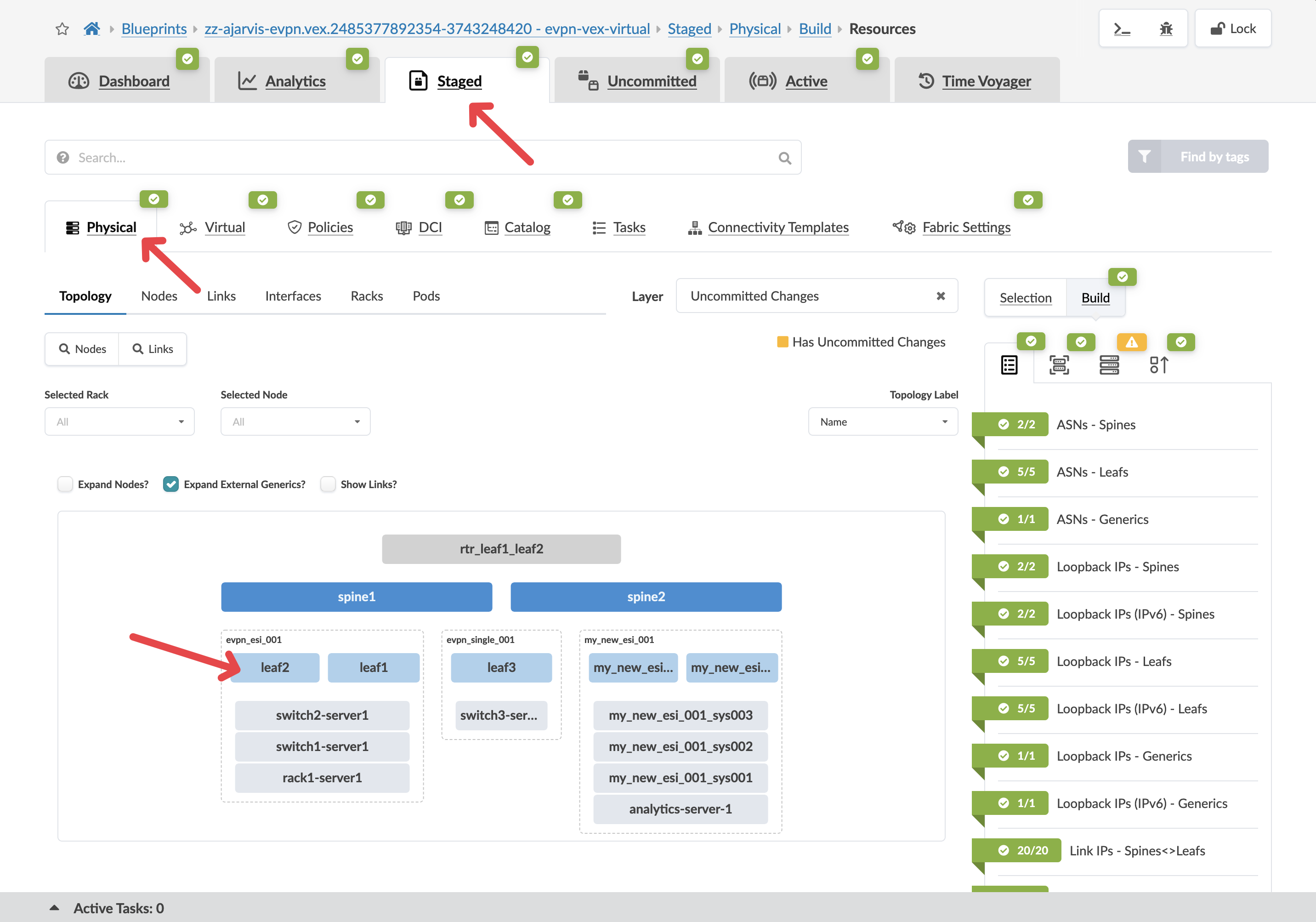
Navigate to menu:Staged[Physical > Topology].
-
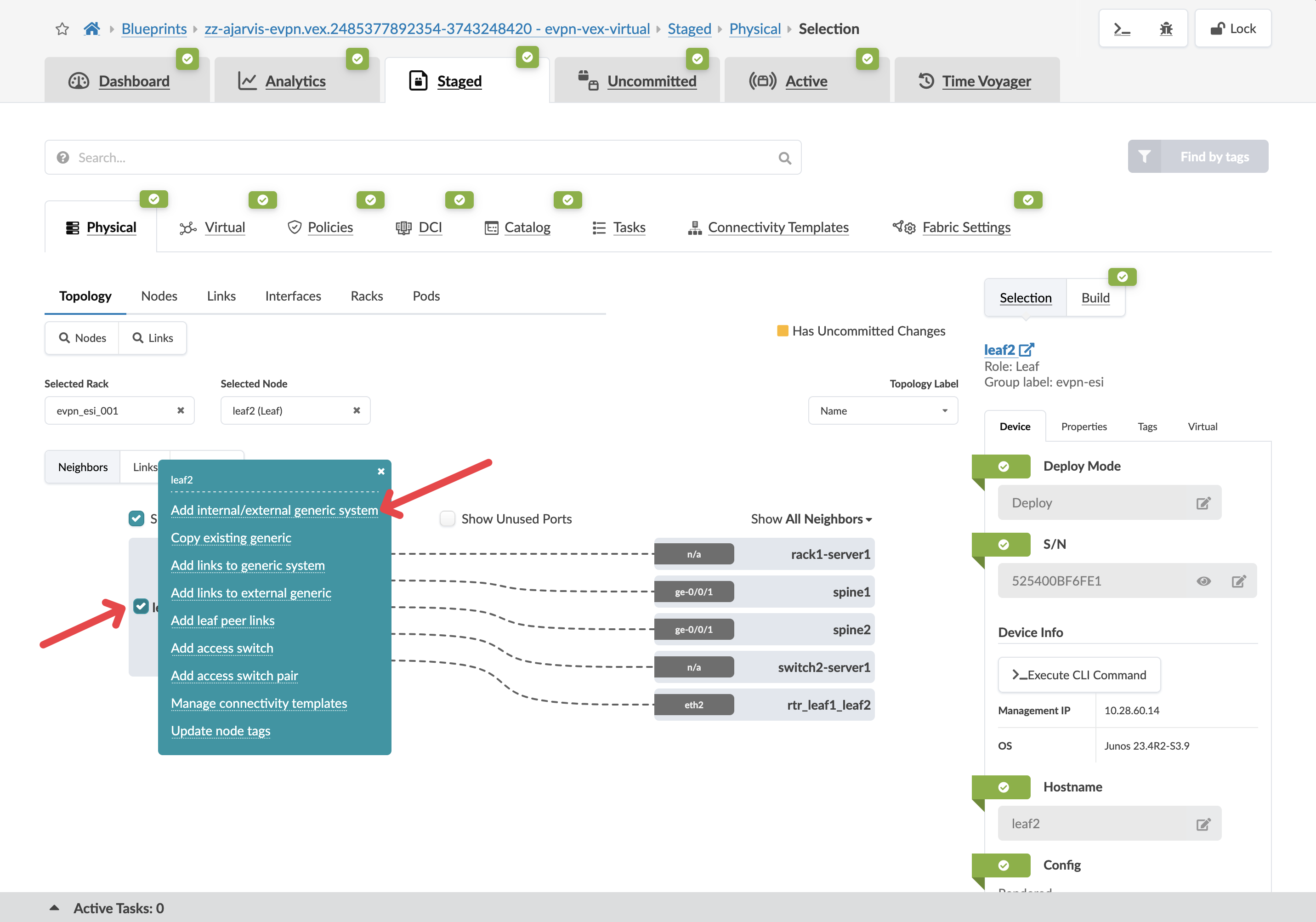
Select leaf2, we will use as a border leaf.
|
What is a border leaf? Border leaf switches sit at the edge of the fabric and handle connectivity to external networks — routers, firewalls, or the WAN. Internal leaf switches connect servers. Border leaves connect the fabric to the outside world. Traffic destined for external systems exits through a border leaf. |
-
Click the box to the left of the device name and select Add internal/external generic system.
| Parameter | Value |
|---|---|
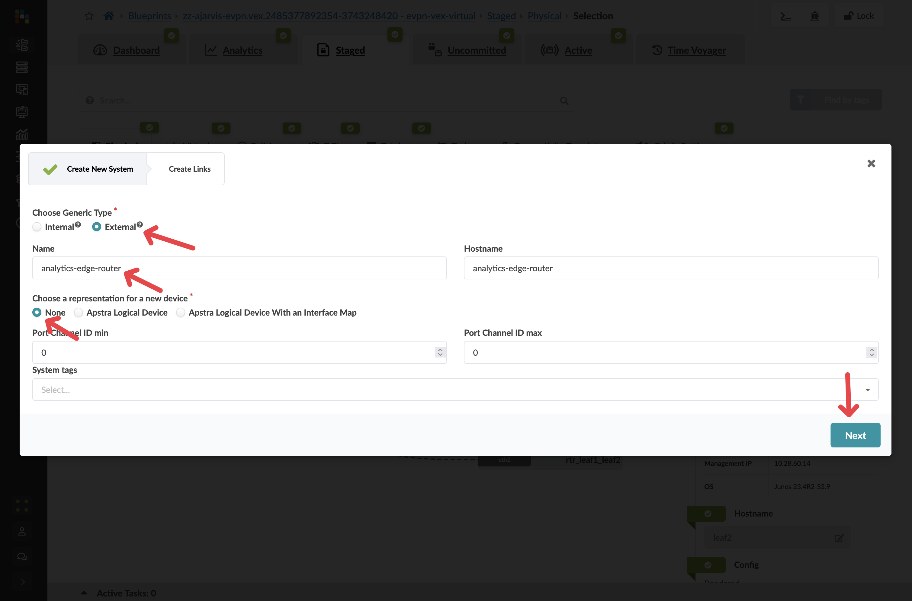
Generic Type |
External |
Name |
analytics-edge-router |
Hostname |
analytics-edge-router |
Logical Device |
None |
-
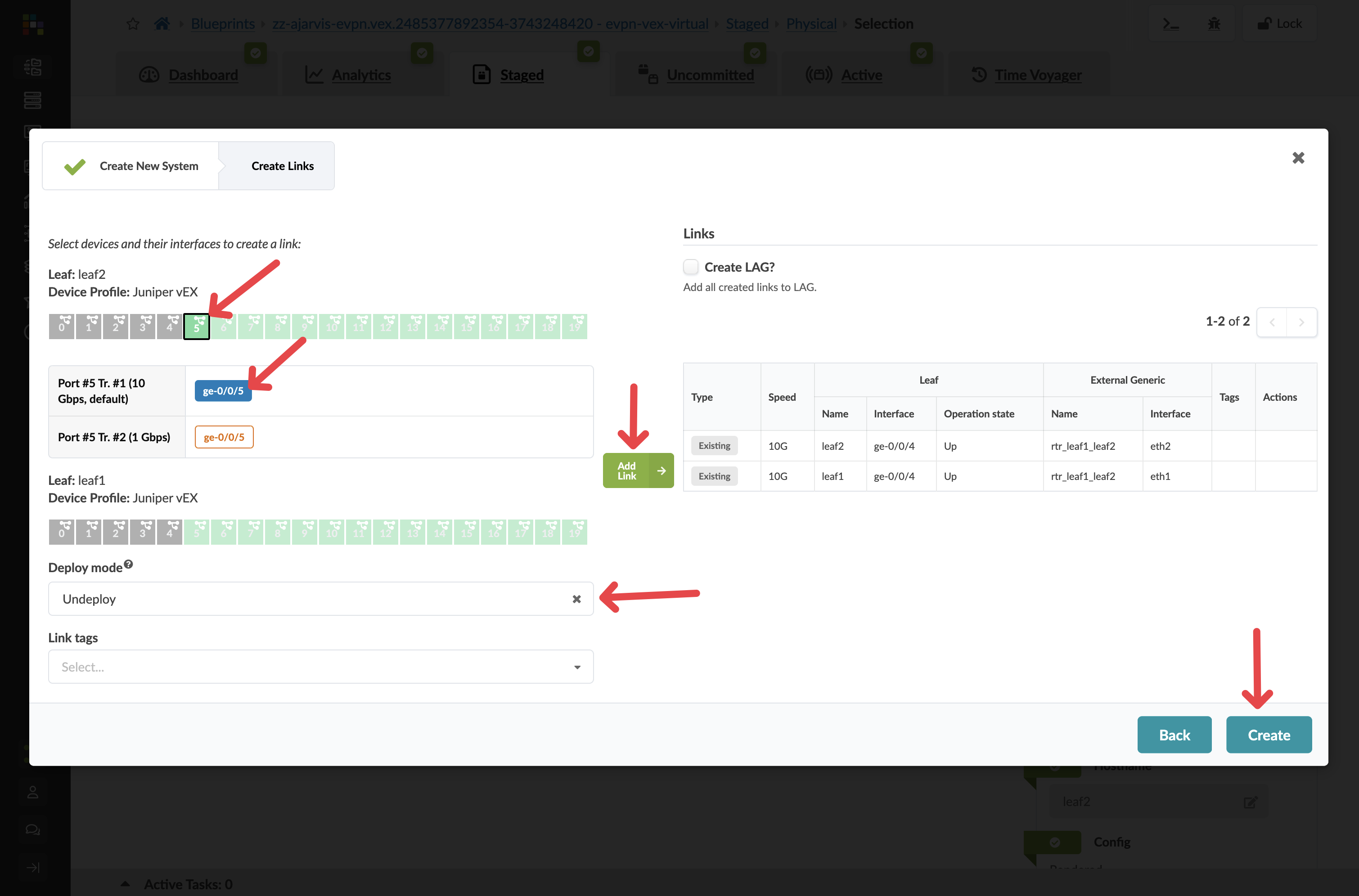
Click Next and configure the links to the external router as follows:
| Parameter | Value |
|---|---|
Port |
Any available port (e.g. port 5) |
Speed |
10Gbps |
Deploy mode |
Undeploy |
Tag |
Router |
|
Undeploy means the connection is fully modelled in the blueprint — Apstra has generated all the configuration — but will not push it to any switch until you change this to Deploy. When the physical router arrives and is cabled in, that one field change activates the entire configuration. |
-
Click Create.
Configuring the router’s properties
-
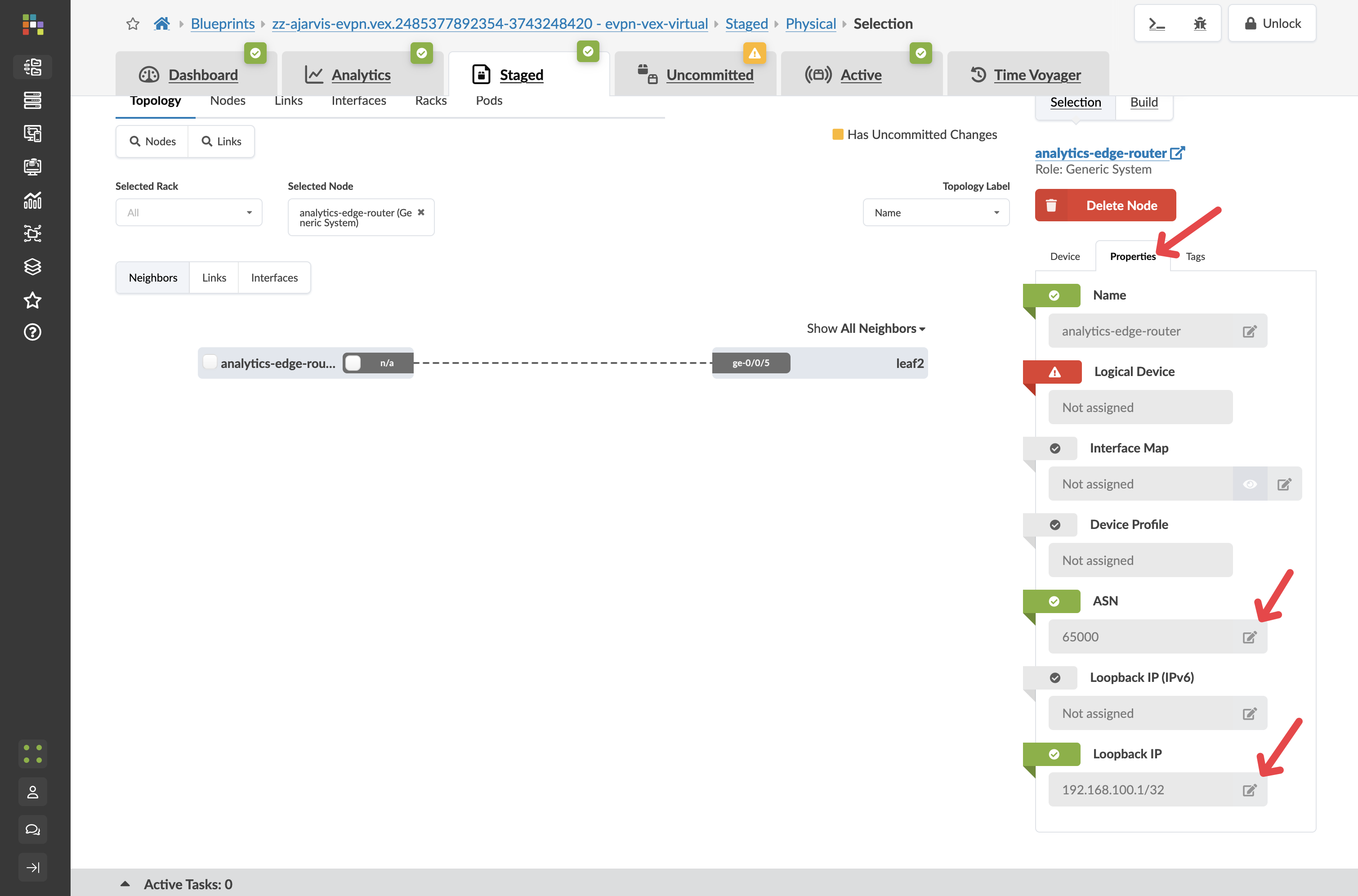
Click on your analytics-edge-router in the topology. image::test_drive/egs_4.png[External router properties tab]
-
Click the Properties tab.
-
Edit each field to reflect the below information.
| Parameter | Value |
|---|---|
ASN |
65000 |
Loopback IP |
192.168.100.1/32 |
|
Why do we need an ASN? BGP (Border Gateway Protocol) — the routing protocol used here — identifies each participant by a unique Autonomous System Number (ASN). The external router must have a different ASN from the fabric switches so that BGP treats it as a trusted external peer rather than part of the fabric. These two values — ASN and loopback IP — are all Apstra needs to generate the full peering configuration on the border leaf. |
Creating the BGP peering connectivity template
Connectivity templates work for external routing sessions, not just servers. Here you will create one that configures the BGP session between the border leaf and the external router.
-
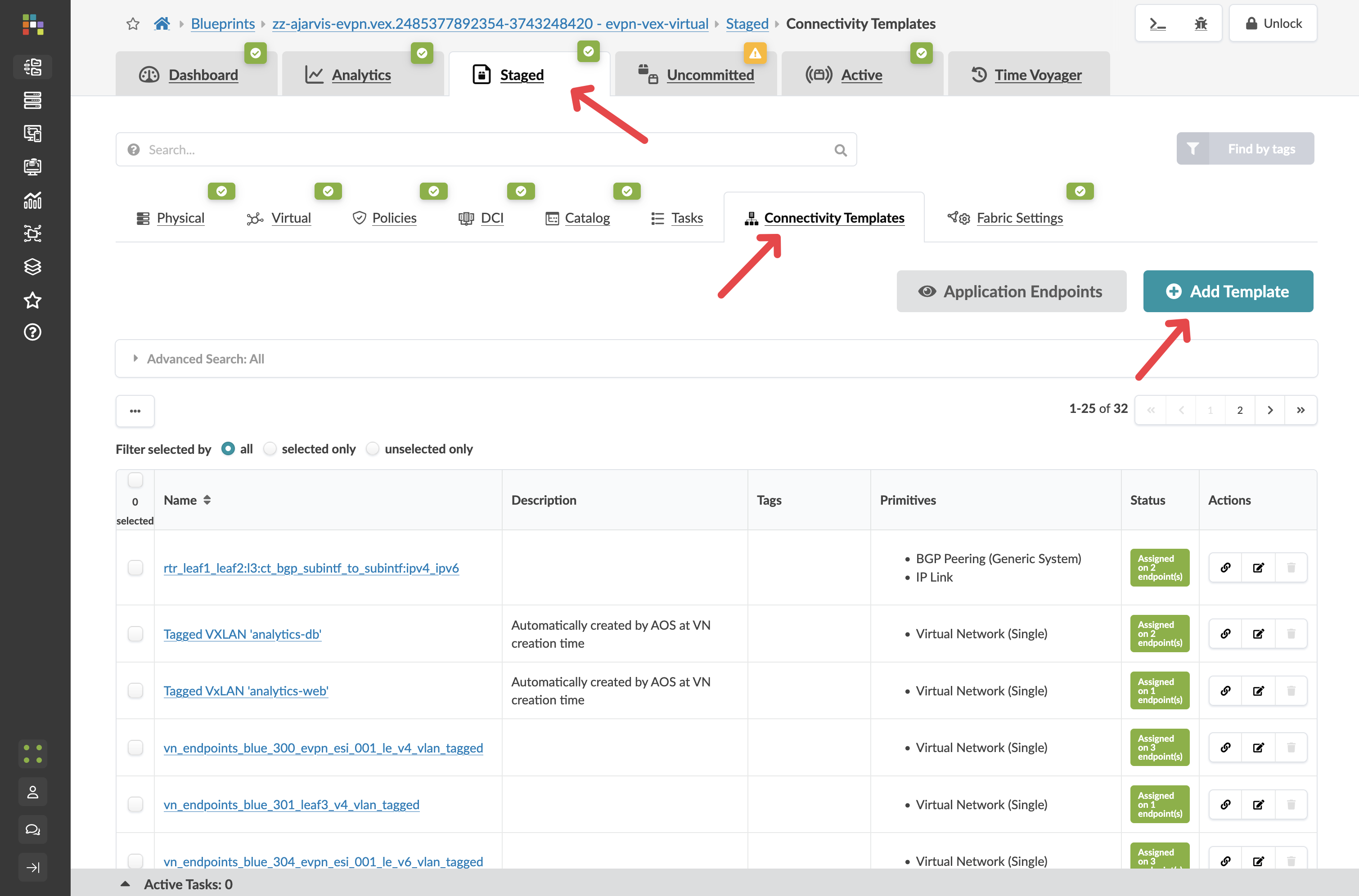
Navigate to menu:Staged[Connectivity Templates].
-
Click Add Template and name it analytics-external-peering.
-
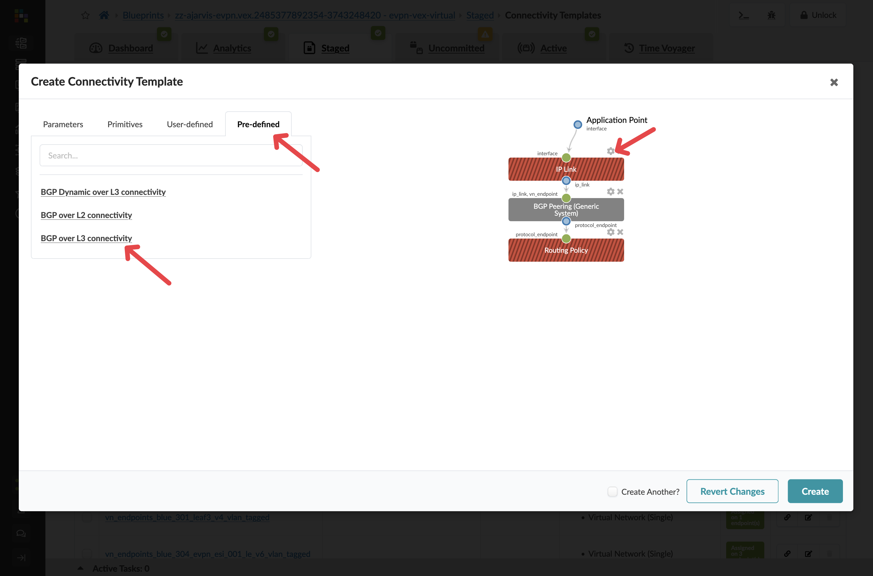
Click the Predefined Templates tab.
-
Select BGP over L3 Connectivity.
-
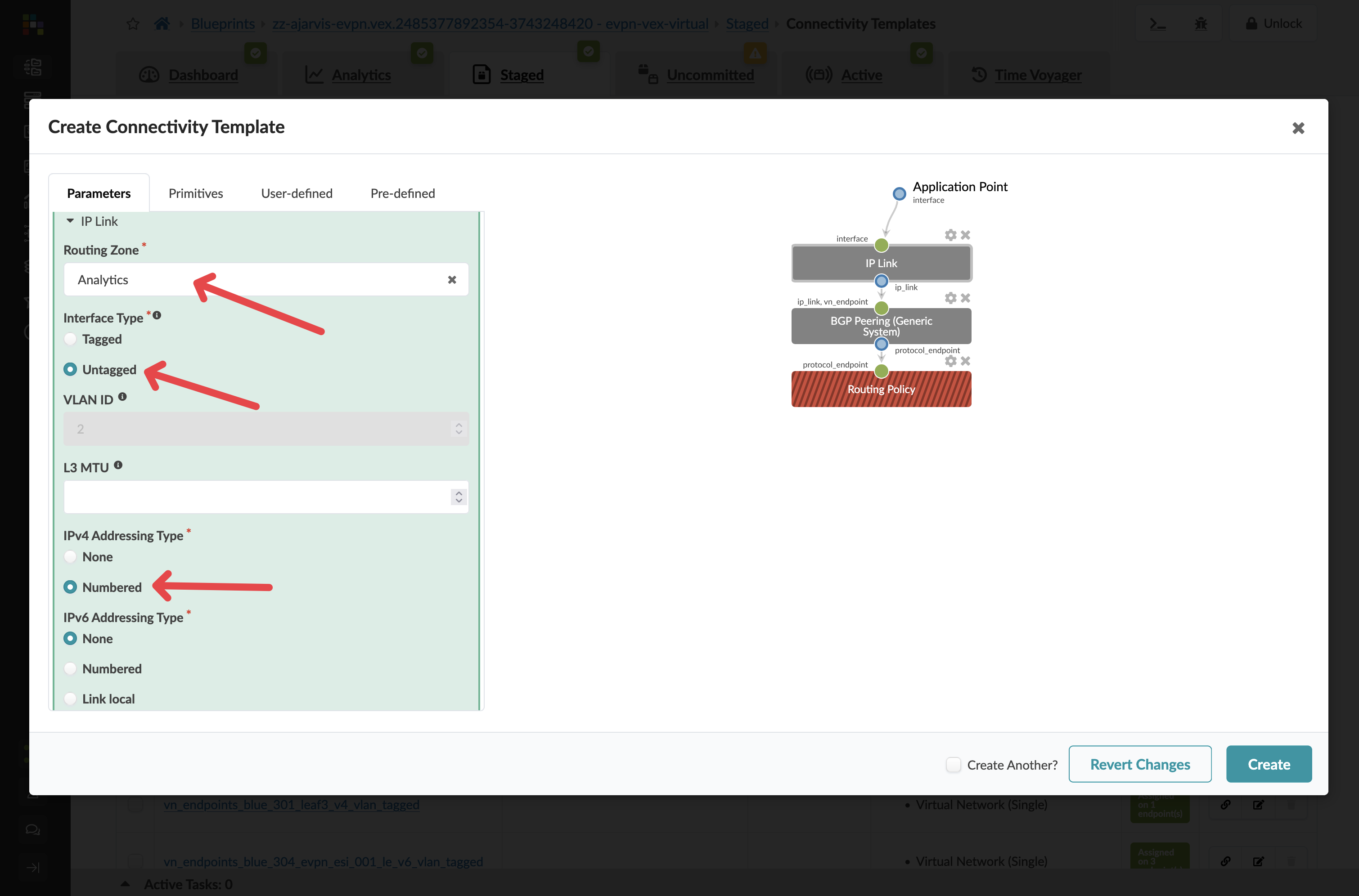
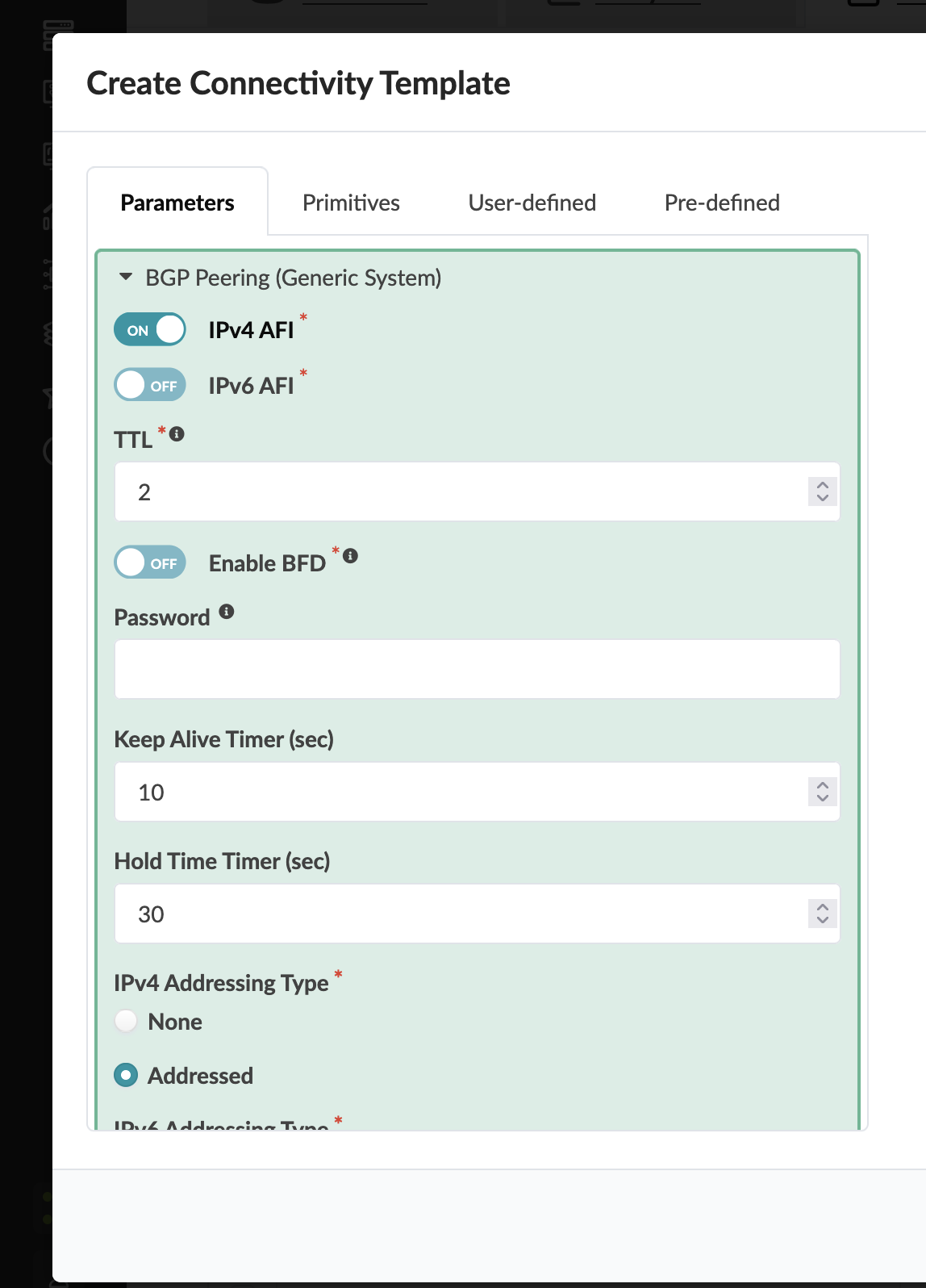
Click the cog next to the IP Link box.
Configure the IP link as follows:
| Parameter | Value |
|---|---|
Routing Zone |
Analytics |
Interface Type |
Untagged |
IPv4 Addressing Type |
Numbered |
|
You are attaching this BGP session to Analytics VRF because the external router doubles as the Layer 3 gateway for that network — the one you deliberately left without an IP gateway on the leaf switches. Traffic from the web tier exits the fabric through this BGP session and is inspected by the firewall before going anywhere else. |
-
Leave the BGP Peering section at its defaults.
-
For Routing Policy you can see on the right hand side, select Default Immutable Policy.
-
Click Create.
|
The Default Immutable Policy is a built-in routing policy that controls which routes the border leaf advertises to and accepts from the external router. Using this is the correct choice for most external peering scenarios — it ensures sensible route advertisements without manual policy configuration. If you have a more complex routing environment with specific policy requirements, you can create your own custom policies and select them here. |
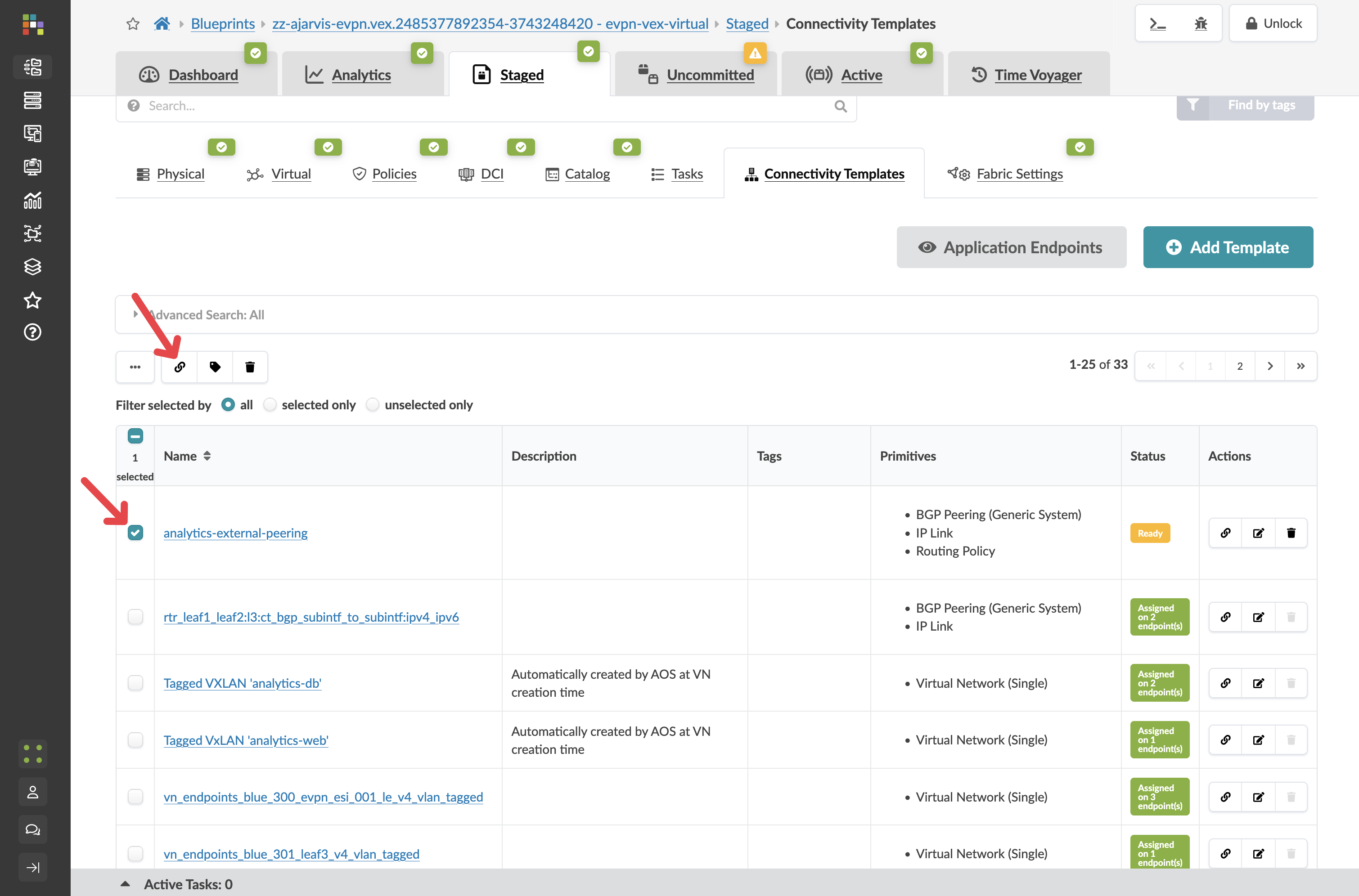
Assigning the template
Now the template has been created, we need to assign it to the interface that will connect to the external router.
-
Select your new analytics-external-peering template in the list.
-
Click Assign.
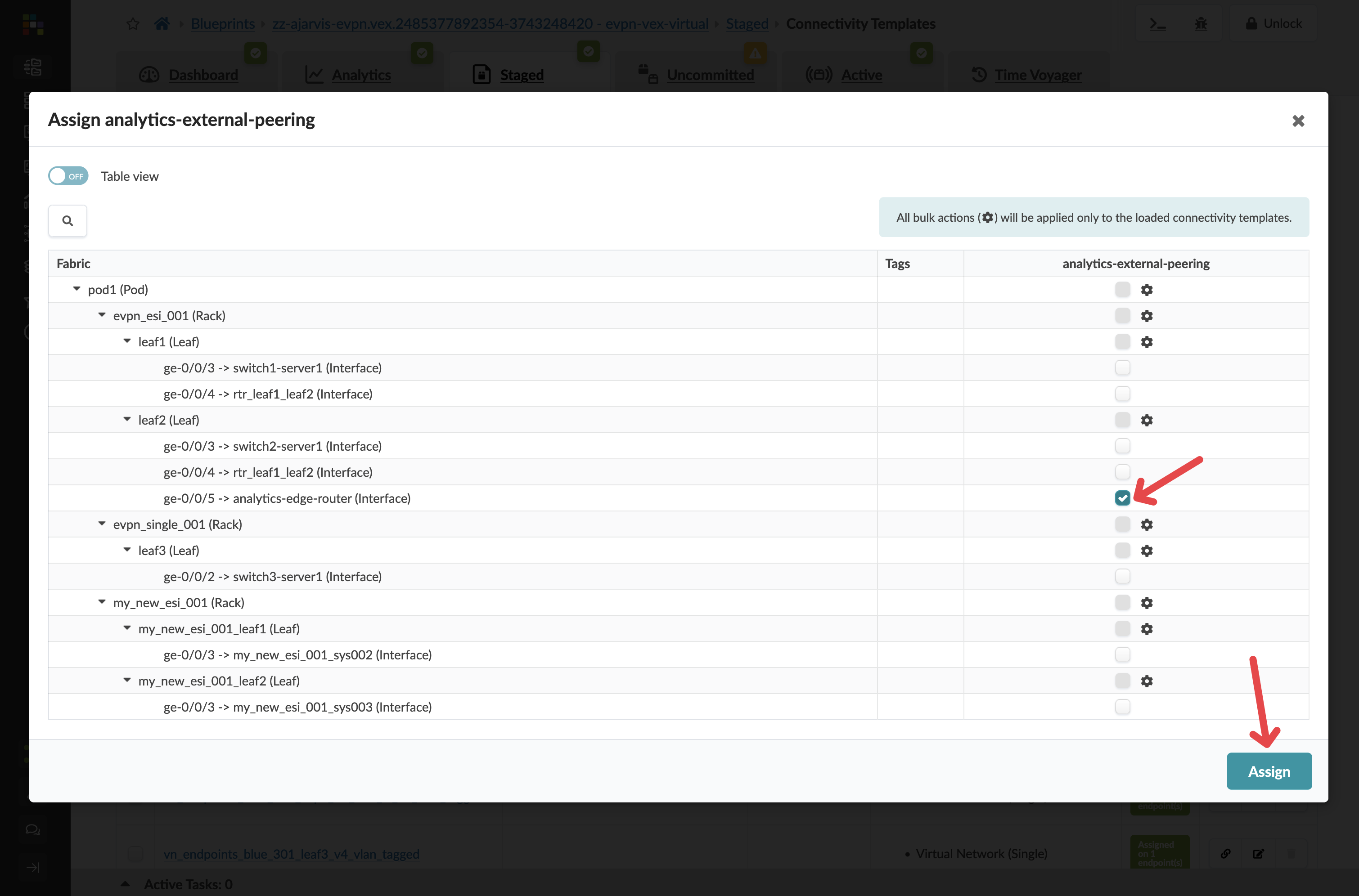
-
Select the interfaces connected to your external router.
-
Click Assign.
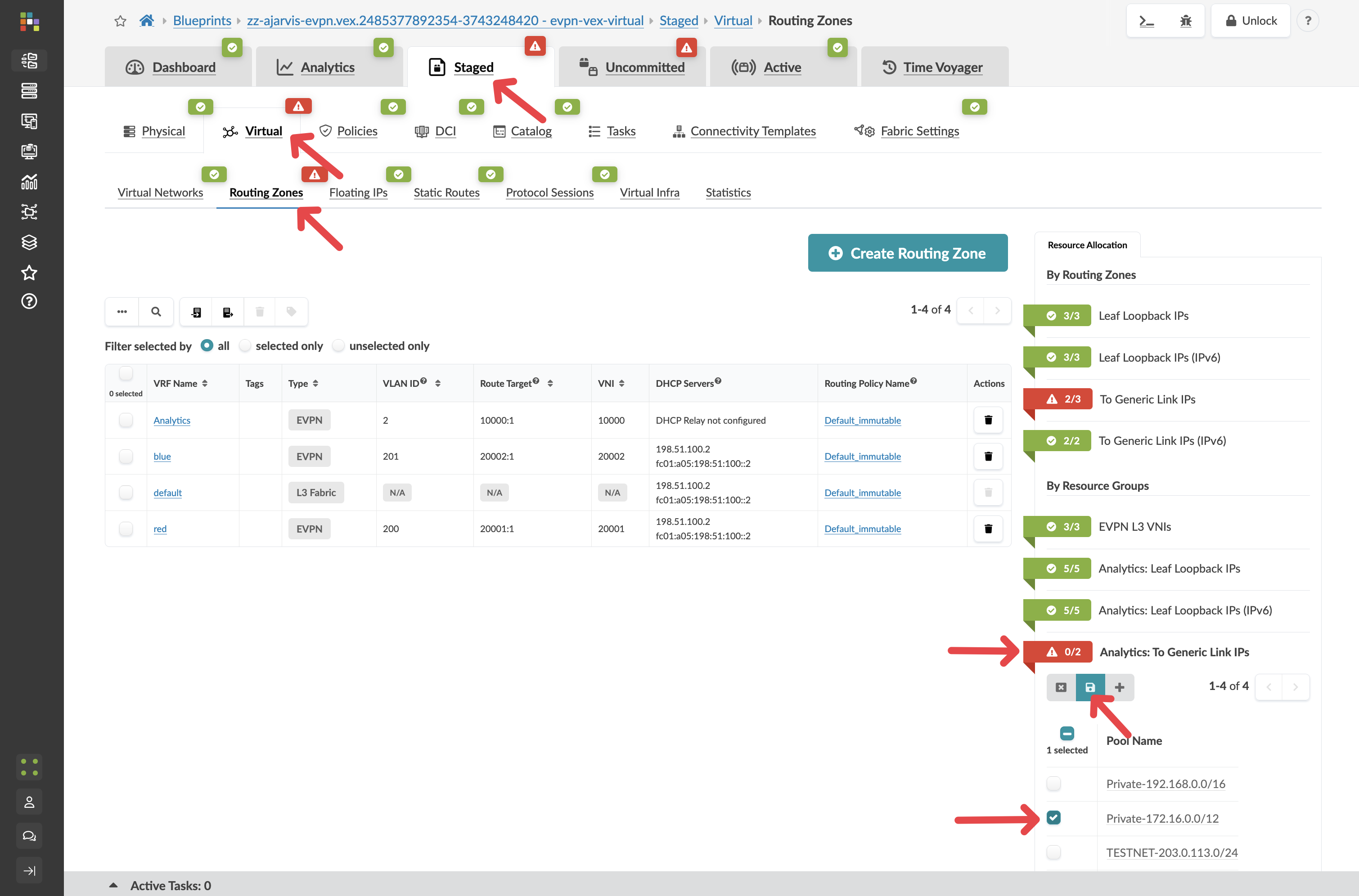
Assigning routing zone resources
After assigning the template, Apstra identifies that the external peering requires additional IP addressing for the point-to-point links between the border leaf and the router. You will see red indicators on the routing zone.
-
Navigate to menu:Staged[Virtual > Routing Zones] and assign any available pool to the red indicators.
-
Assign appropriate resource pools as needed to resolve the red indicators.
-
Select the border leaf switch and check the Incremental Configuration tab.
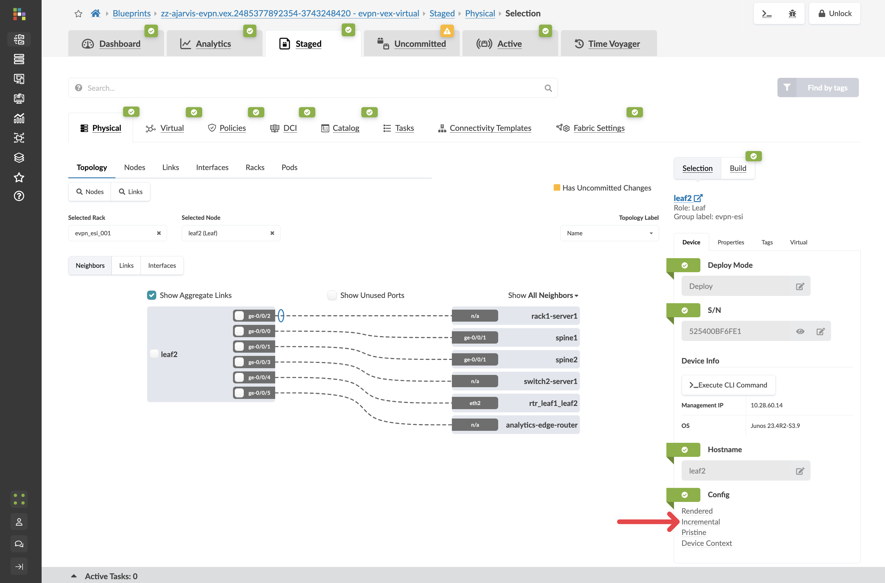
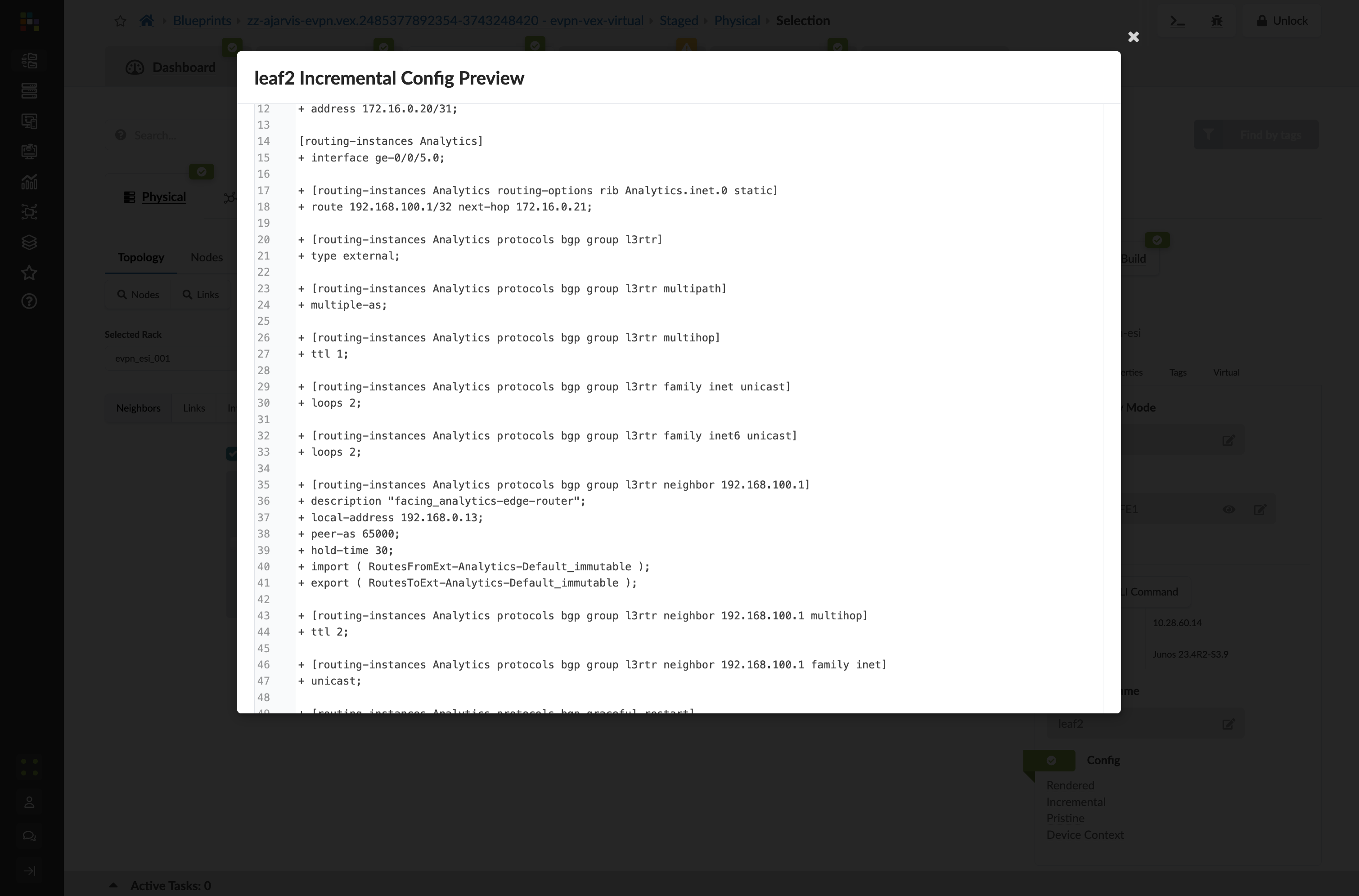
The full BGP peering configuration is staged and ready to deploy the moment the physical router is in place.
-
Click the Uncommitted tab, enter a commit message such as External connectivity for Analytics service staged, and click Commit.