Section 2: Expanding the fabric
In our pretend scenario, your organisation has approved a new Big Data Analytics service. You need to expand the data centre to support it — new physical capacity, a dedicated routing domain for isolation, and two virtual network segments for the web and database tiers.
|
Your scenario: Add a new rack, create a dedicated routing zone (VRF) for the analytics workload, and build virtual networks for a web tier and a database tier — all through the Apstra UI, without touching a command line. |
Adding a new rack
In a traditional environment, adding a rack means planning IP addressing, ASN assignments, underlay BGP, and overlay EVPN — and then manually configuring each new switch. That process typically takes days.
|
Before you start, consider this: How long would it take your team to add a pair of switches from scratch today? Many organisations report this taking the better part of a week per rack, once you factor in IP planning, ASN allocation, BGP configuration, EVPN setup, and testing. That is the baseline you are comparing against. |
-
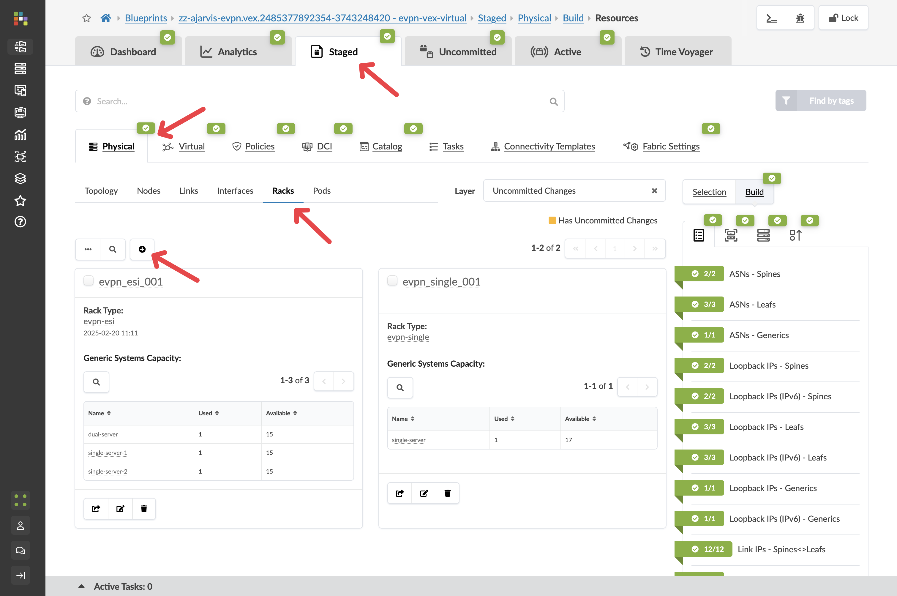
Navigate to menu:Staged[Physical > Racks].
-
Click the Add Racks button (+).
-
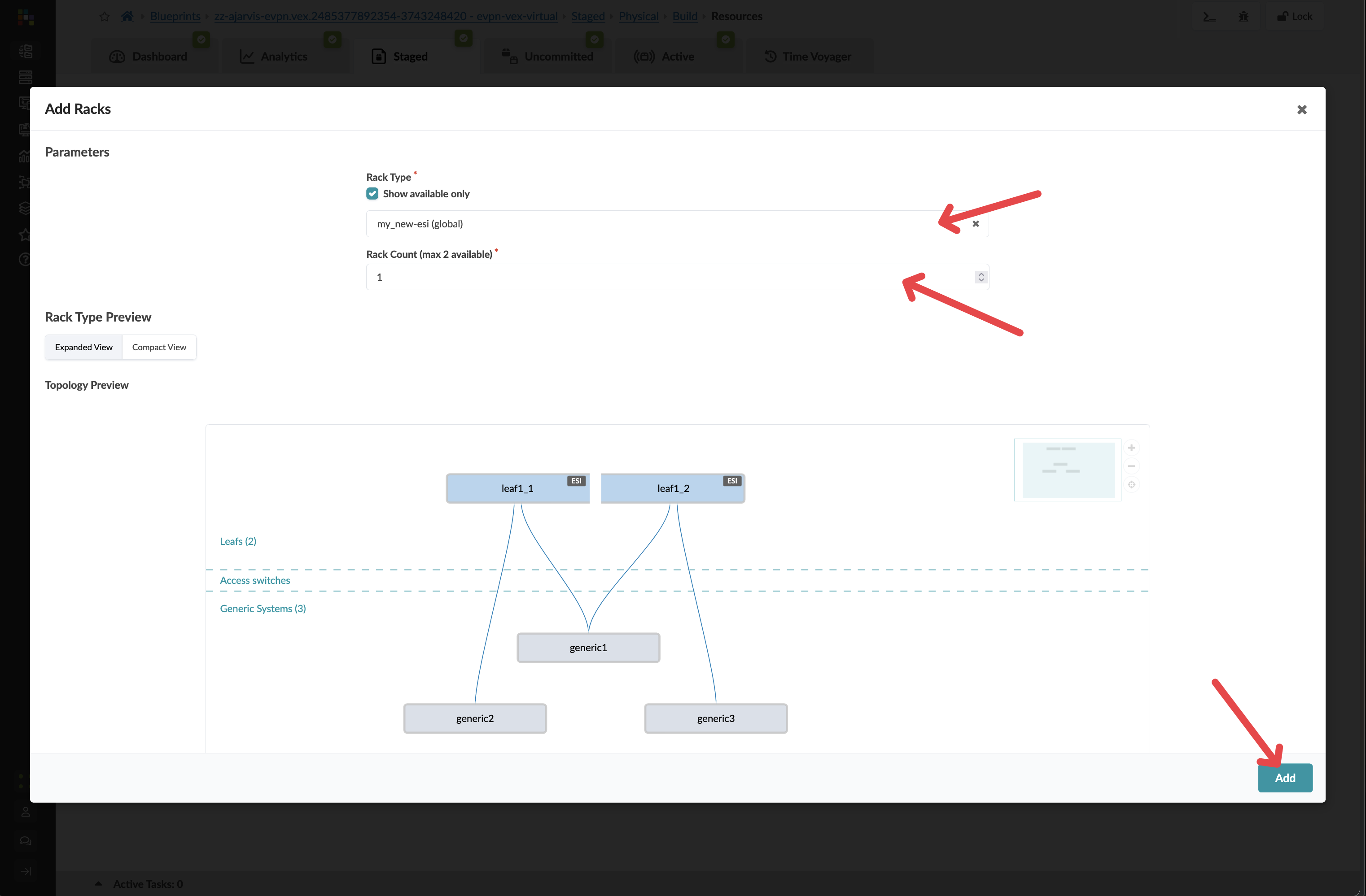
From the Rack Type drop-down, select evpn-esi.
|
What is evpn-esi? EVPN-ESI is the standard dual-leaf rack design for modern data centres. It uses two leaf switches working in tandem — EVPN (Ethernet VPN) carries the overlay networking across the fabric, and ESI-LAG (Ethernet Segment Identifier Link Aggregation) allows servers to connect to both leaf switches simultaneously for redundancy. If one leaf fails, the other keeps the server online. This is the most common architecture in use today. |
-
Leave the count at 1.
-
Click Add.
|
You have just staged a new rack without any physical hardware present. Apstra can model the entire expansion before the switches arrive on site. When they do arrive, you rack them, cable them to the spines, and Apstra pushes the complete configuration automatically. |
Assigning device profiles
A device profile tells Apstra the physical characteristics of a switch — which ports exist, their speeds, and how they map to the logical design. In this virtual lab environment, you will need to assign the correct virtual switch profile to the new leaf switches.
-
Navigate to menu:Staged[Physical > Device Profiles].
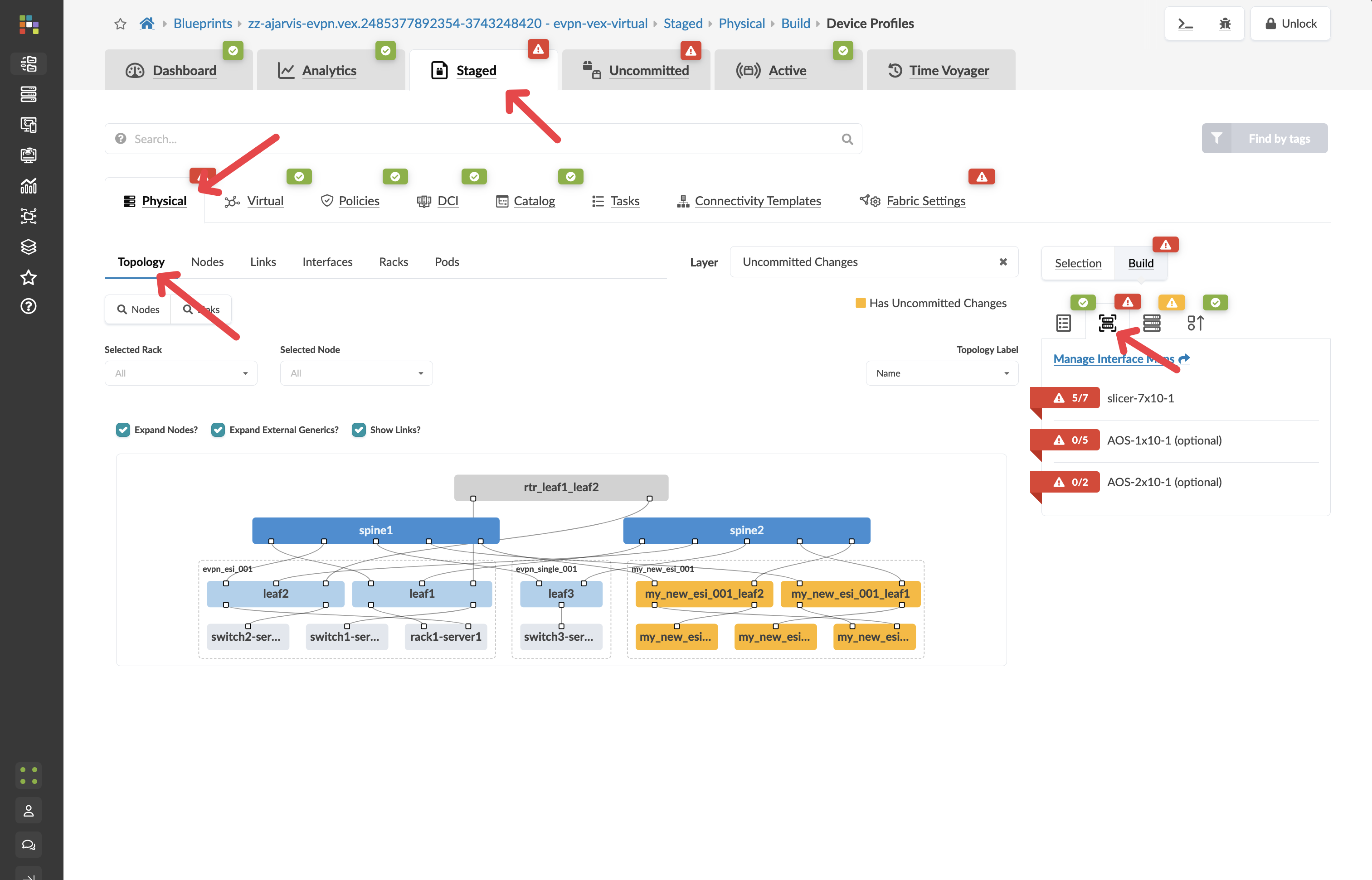
You will see red indicators on the new leaf switches. This is expected — Apstra is waiting for you to confirm which hardware profile to use before it can generate configuration for these devices.
-
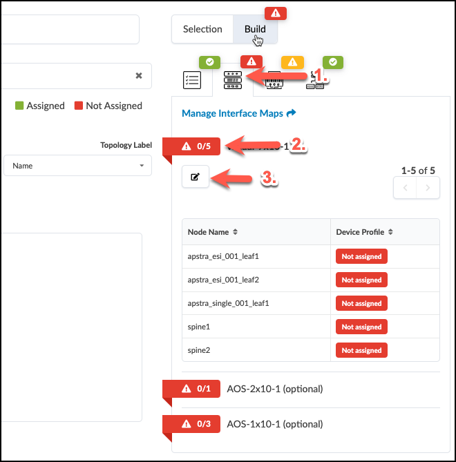
Click the red indicator on a new leaf switch.
-
Select Juniper_vEX__slicer-7x10⁻¹ for each new leaf switch.
-
Click Update Assignments.
Reviewing what Apstra has generated automatically
Now that the hardware profile is assigned, Apstra can generate full device configuration. Let’s see what it has produced — before a single commit has happened.
-
Navigate to menu:Staged[Physical > Topology].
-
Click on one of your new leaf switches.
-
Click the Rendered Configuration tab.
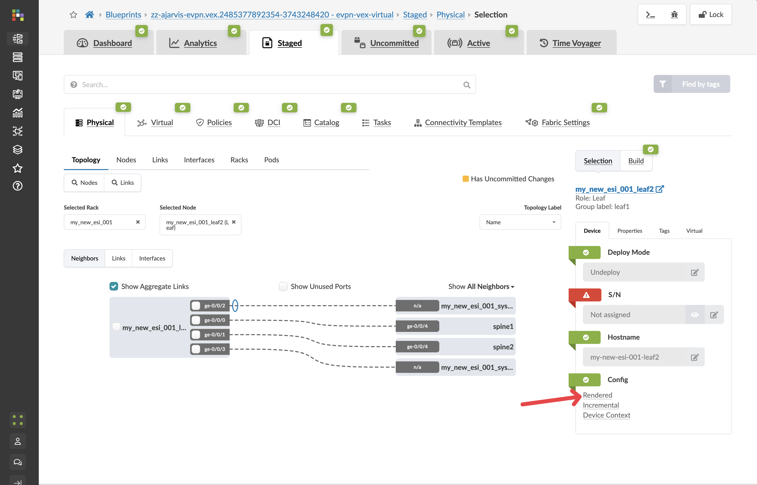
Apstra has automatically assigned unique ASNs from your resource pools, allocated IP addressing for all interfaces, generated the full BGP underlay configuration, built the EVPN overlay, and prepared updates to the existing spine switches so they know about the new leaves.
Not a single line was written manually.
-
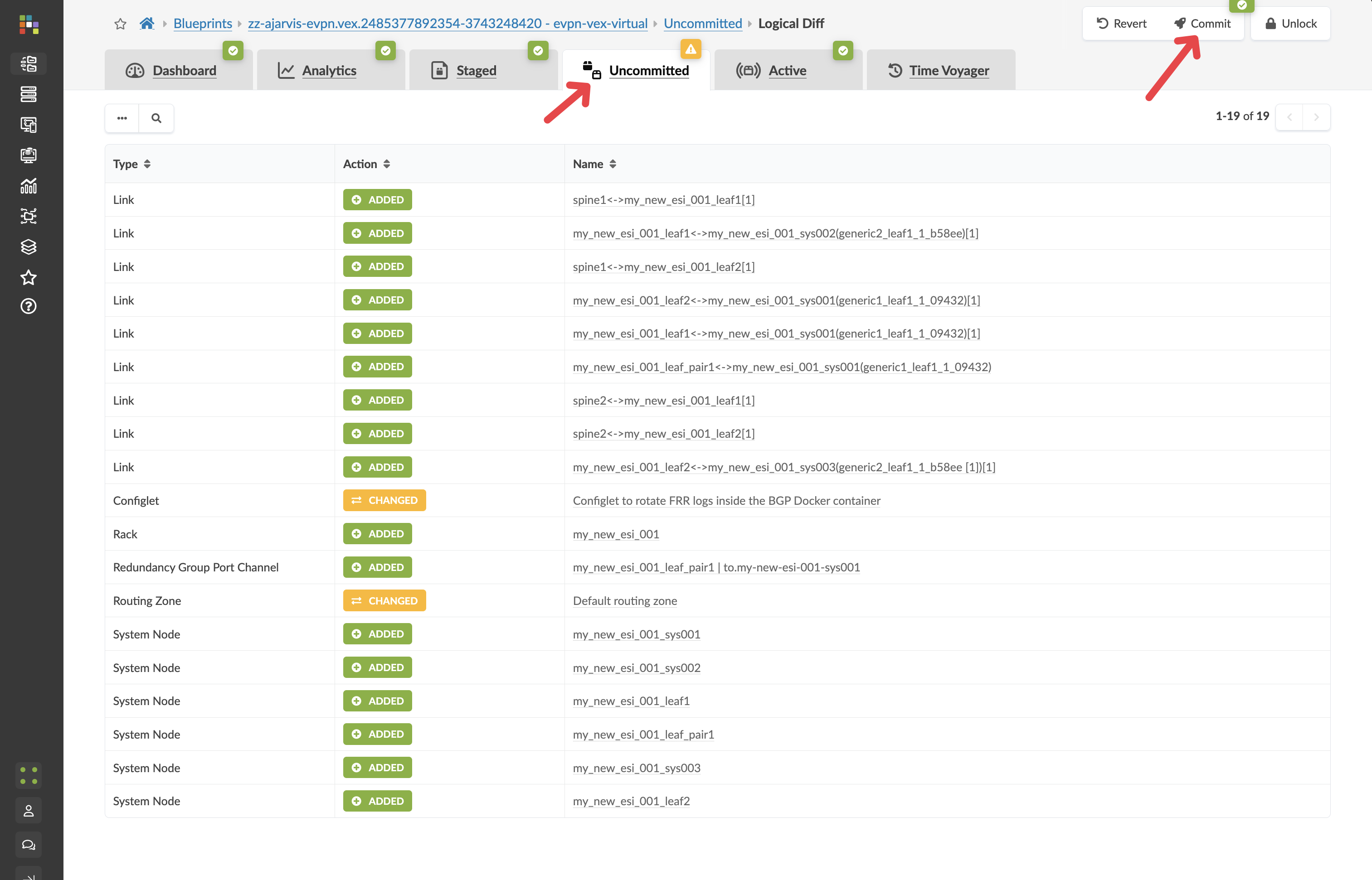
Click the Uncommitted tab to review all staged changes.
|
Look through what is listed here. Apstra has translated one high-level intent — "add a rack of type evpn-esi" — into vendor-specific, best-practice configuration across every device that needs to change. The spine switches are included because they need to peer with the new leaves. You did not have to identify that — Apstra worked it out from the blueprint model. |
Your first commit
A commit in Apstra is not just a save. When you click Commit, Apstra calculates every configuration change required across every affected device, validates the result against the blueprint intent, and pushes it all simultaneously. Each commit also creates a permanent, reversible snapshot of the network state — you will use this later in the lab.
Getting into the habit of writing a meaningful commit message matters. It becomes part of the permanent change history that anyone on your team can review, and it is what you will rely on when you need to find a specific point in time to roll back to.
-
Navigate to menu: Uncommited
-
Enter a commit message such as Prestaged new analytics rack.
-
Click Commit.
Creating a routing zone (VRF)
A routing zone in Apstra is a VRF — a virtual routing table that creates a completely separate network domain within the fabric. The analytics workload needs its own routing zone so that its traffic stays isolated from other services. Without this isolation, any server in the fabric could potentially reach the analytics systems, which is a security and operational risk.
In a traditional environment, creating a VRF means configuring route distinguishers, route targets, and import/export policies on every relevant switch by hand. Here, it takes one field.
-
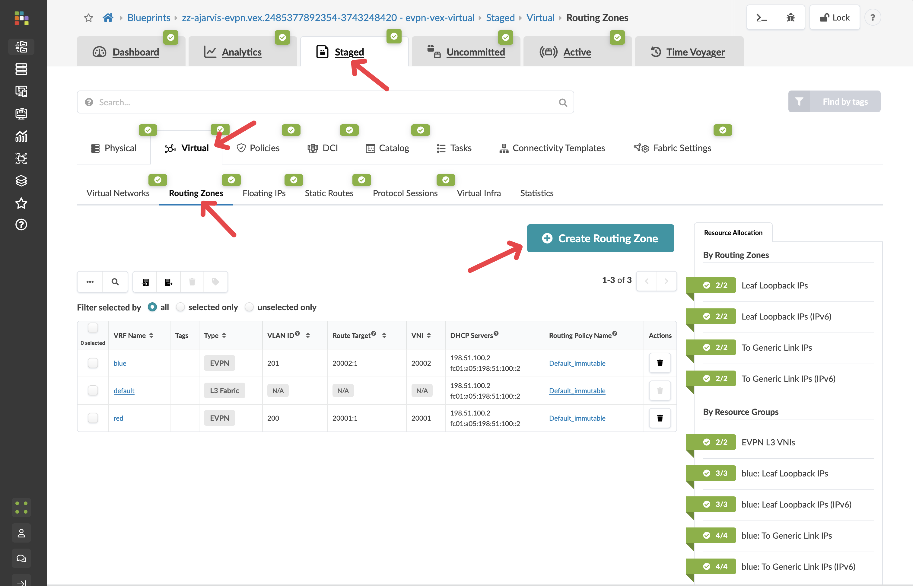
Navigate to menu:Staged[Virtual > Routing Zones].
-
Click Create Routing Zone.
-
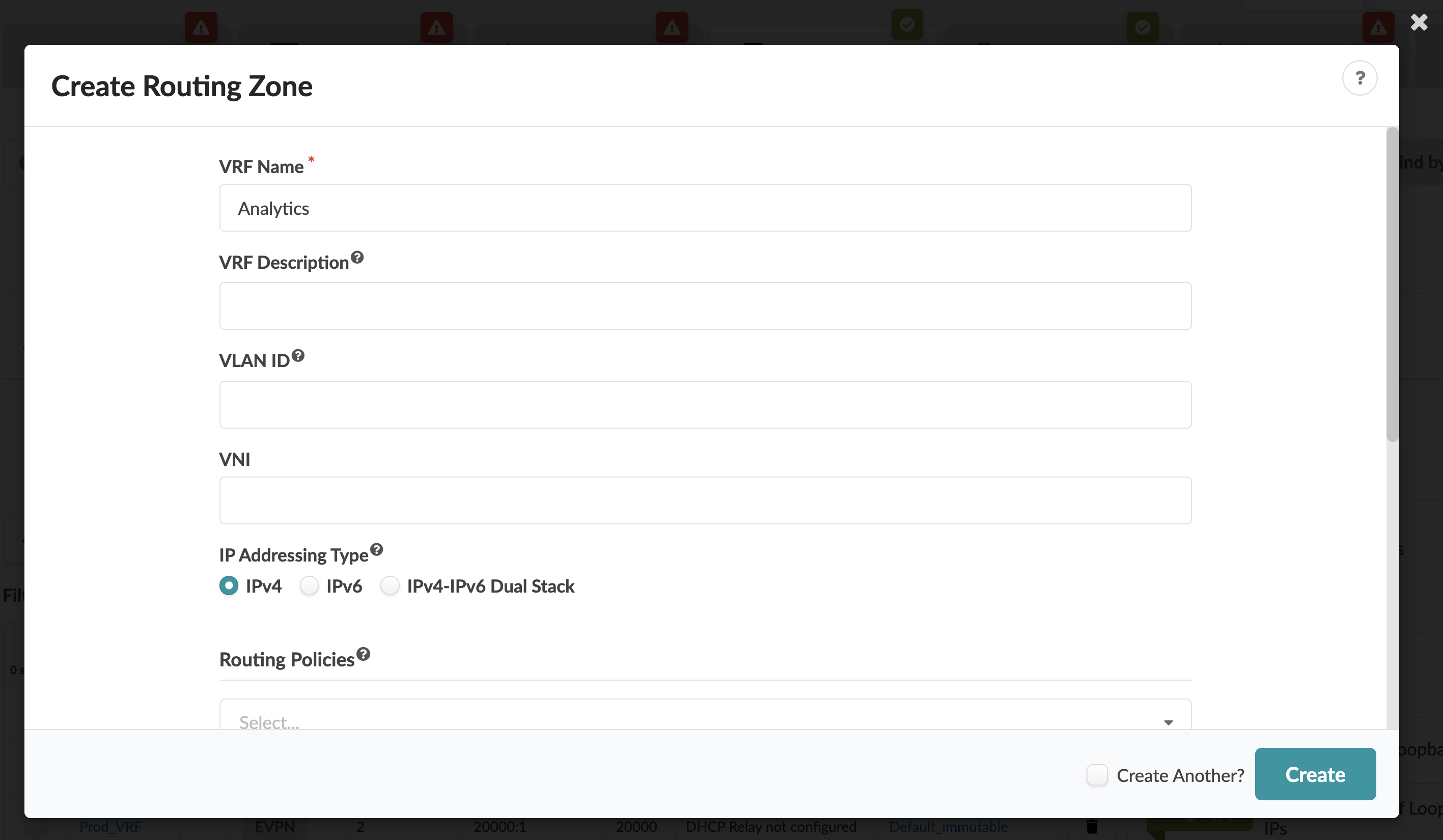
Enter Analytics as the name.
|
That is the only required field. Apstra determines the route distinguisher, route targets, and default routing policies automatically — derived from the resource pools you set up when the system was configured, following the same best practices for every routing zone you create. |
-
Set to IPv4 Only
-
Leave all other fields at their defaults.
-
Click Create.
Check the incremental configuration
-
Navigate to menu:Staged[Physical > Devices] and select any leaf switch. image::test_drive/incrimental_leaf.png[Navigating to the incremental config tab]
-
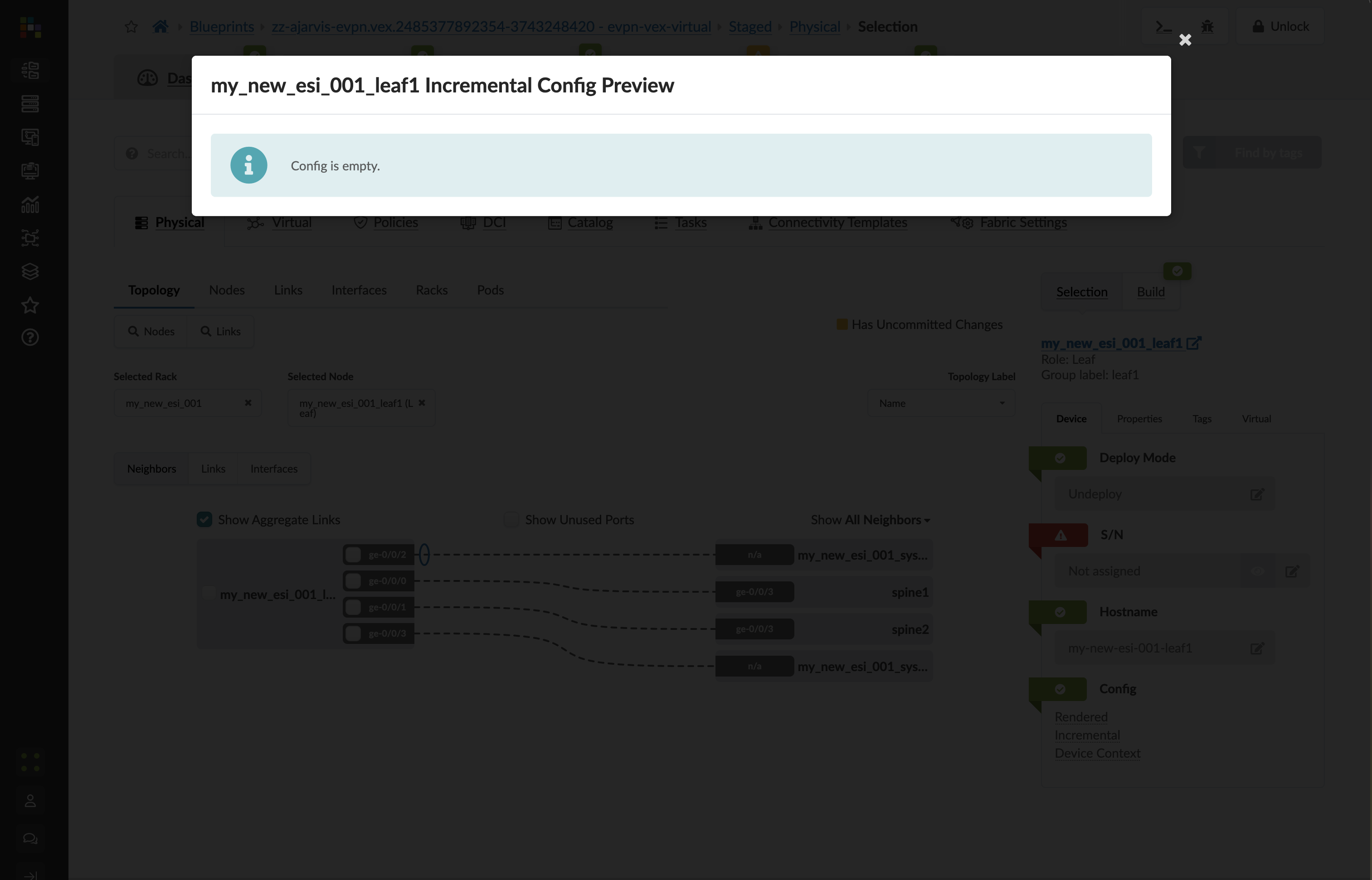
Click the Incremental Configuration tab.
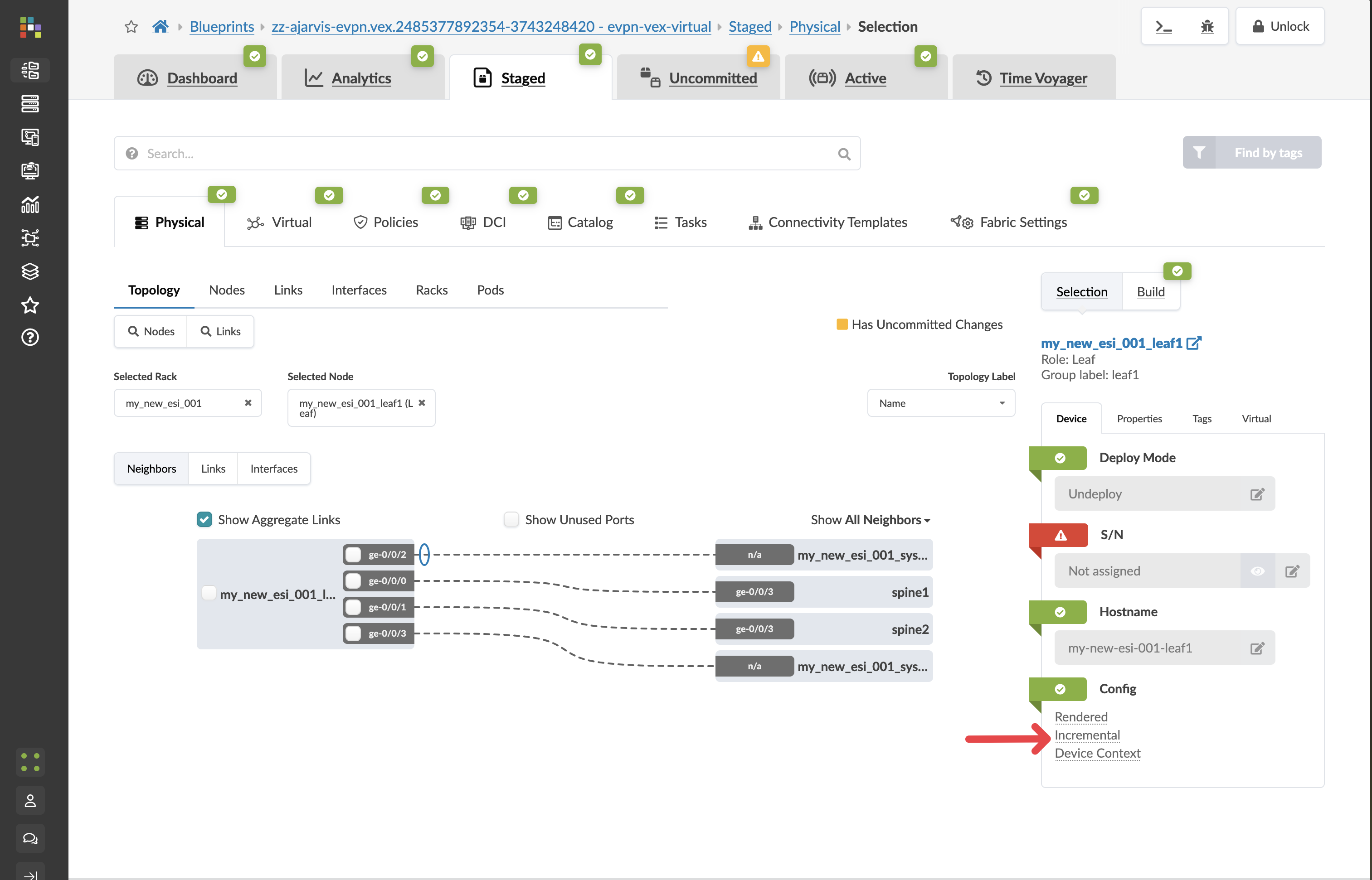
The incremental configuration is empty right now, and that is correct. Apstra only pushes a VRF to a switch when a virtual network using that VRF is assigned to that switch. Creating the routing zone just registers the intent — the configuration follows when something actually needs it.
-
Click the Uncommitted tab, enter a commit message such as Added Analytics routing zone, and click Commit.
Creating virtual networks
The analytics service needs two separate network segments. The web tier needs extra security — its traffic should be inspected by an external firewall before routing anywhere. The database tier is internal-only and can be routed directly within the fabric. These two requirements lead to two different virtual network designs.
Web tier (Layer 2 only)
-
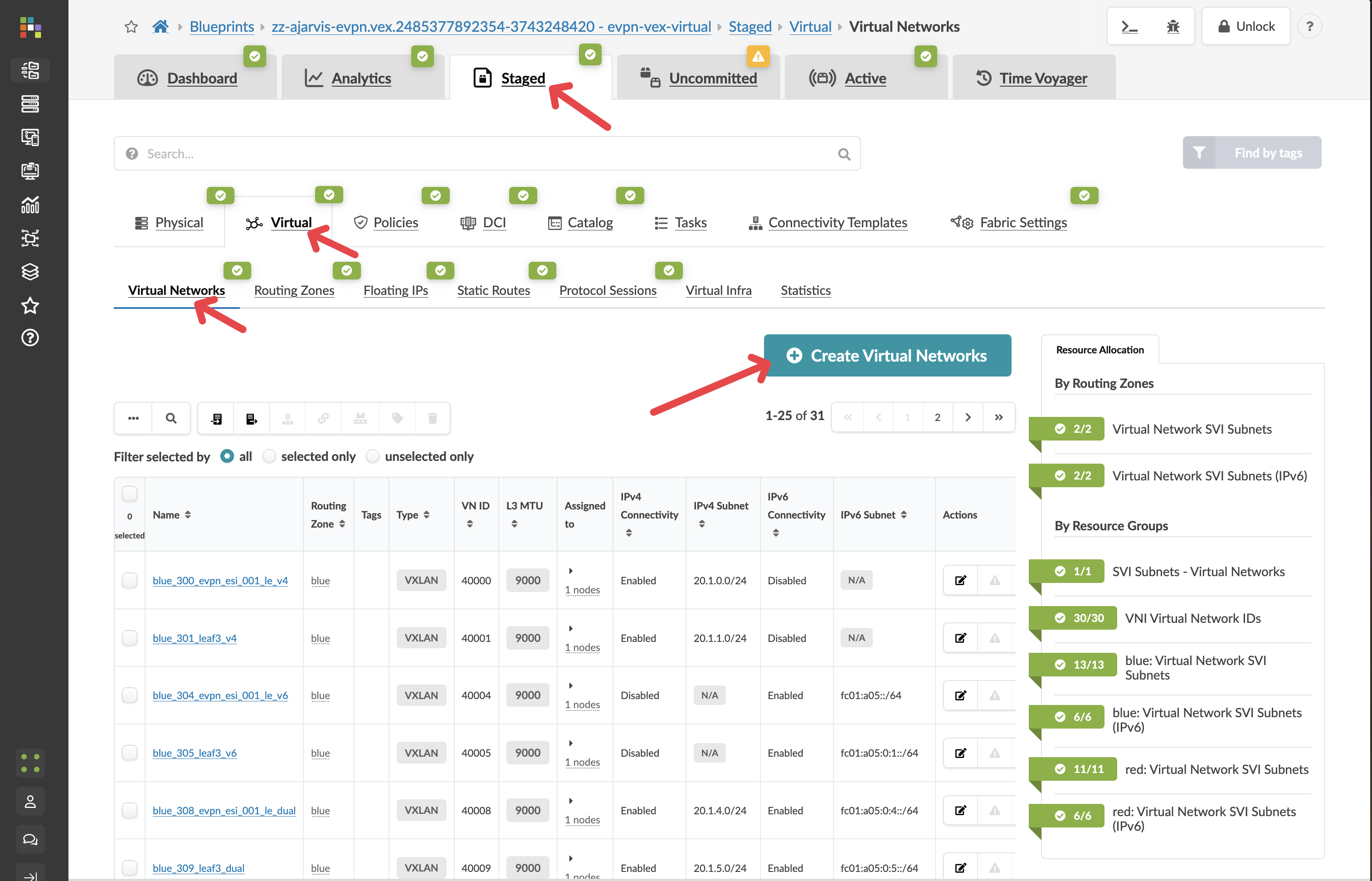
Navigate to menu:Staged[Virtual > Virtual Networks].
-
Click Create Virtual Network.
| Parameter | Value |
|---|---|
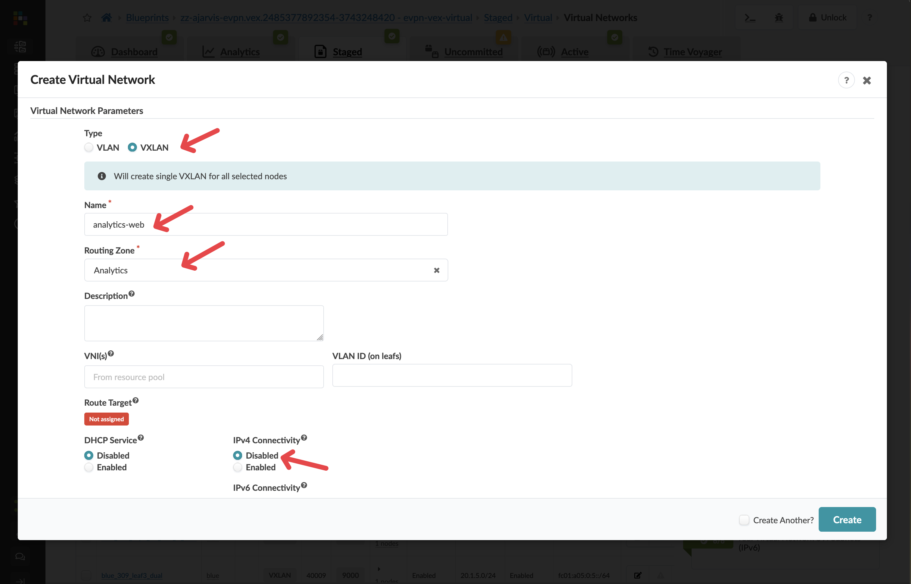
Type |
VXLAN |
Name |
analytics-web |
Routing Zone |
Analytics |
IPv4 Connectivity |
Disabled |
IPv6 Connectivity |
Disabled |
|
Why disable IPv4 Connectivity? Disabling it creates a Layer 2 only (bridged) network — the VXLAN tunnel carries Ethernet frames, but there is no IP gateway on the leaf switches. The gateway for this segment will sit on an external firewall, so all inter-network routing passes through it. This gives you a dedicated security inspection point for customer-facing web traffic. |
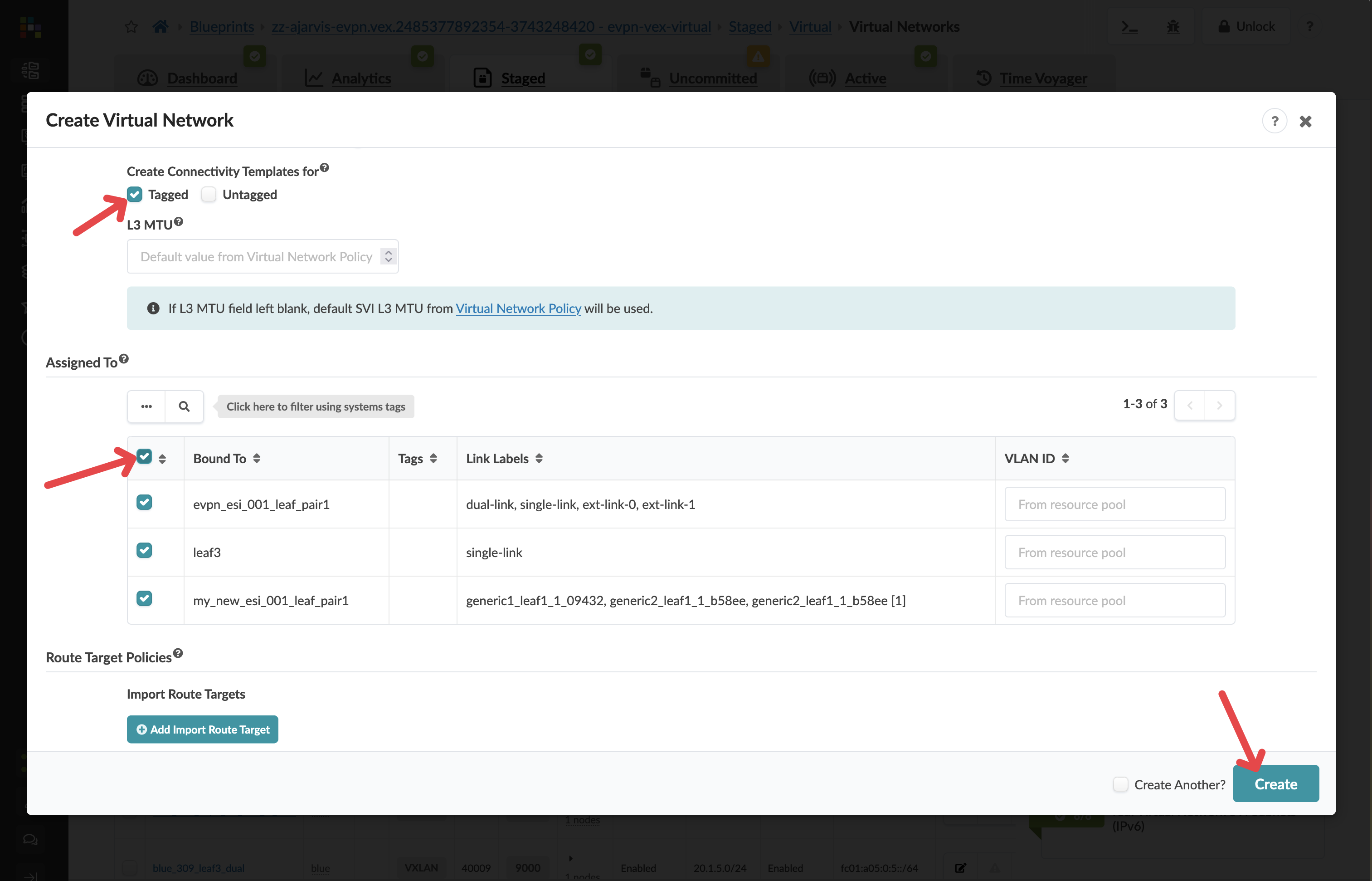
-
In Create Connectivity Templates for, select Tagged.
|
Tagged means the VLAN identifier is preserved on the wire — the switch port carries traffic with an 802.1Q tag, allowing multiple networks to share the same physical interface. This is standard practice for server ports that need to reach more than one network. |
-
In Assigned To, select all racks.
|
We are assigning this network to all racks so that analytics workloads can run on any server in the fabric, not just servers in the new rack. This gives your team flexibility to place workloads wherever capacity is available. |
-
Click Create.
Database tier (Layer 3)
-
Click Create Virtual Network again.
| Parameter | Value |
|---|---|
Type |
VXLAN |
Name |
analytics-db |
Routing Zone |
Analytics |
IPv4 Connectivity |
Enabled |
IPv4 Subnet |
10.1.2.0/24 |
Virtual Gateway IP |
10.1.2.1 |
IPv6 Connectivity |
Disabled |
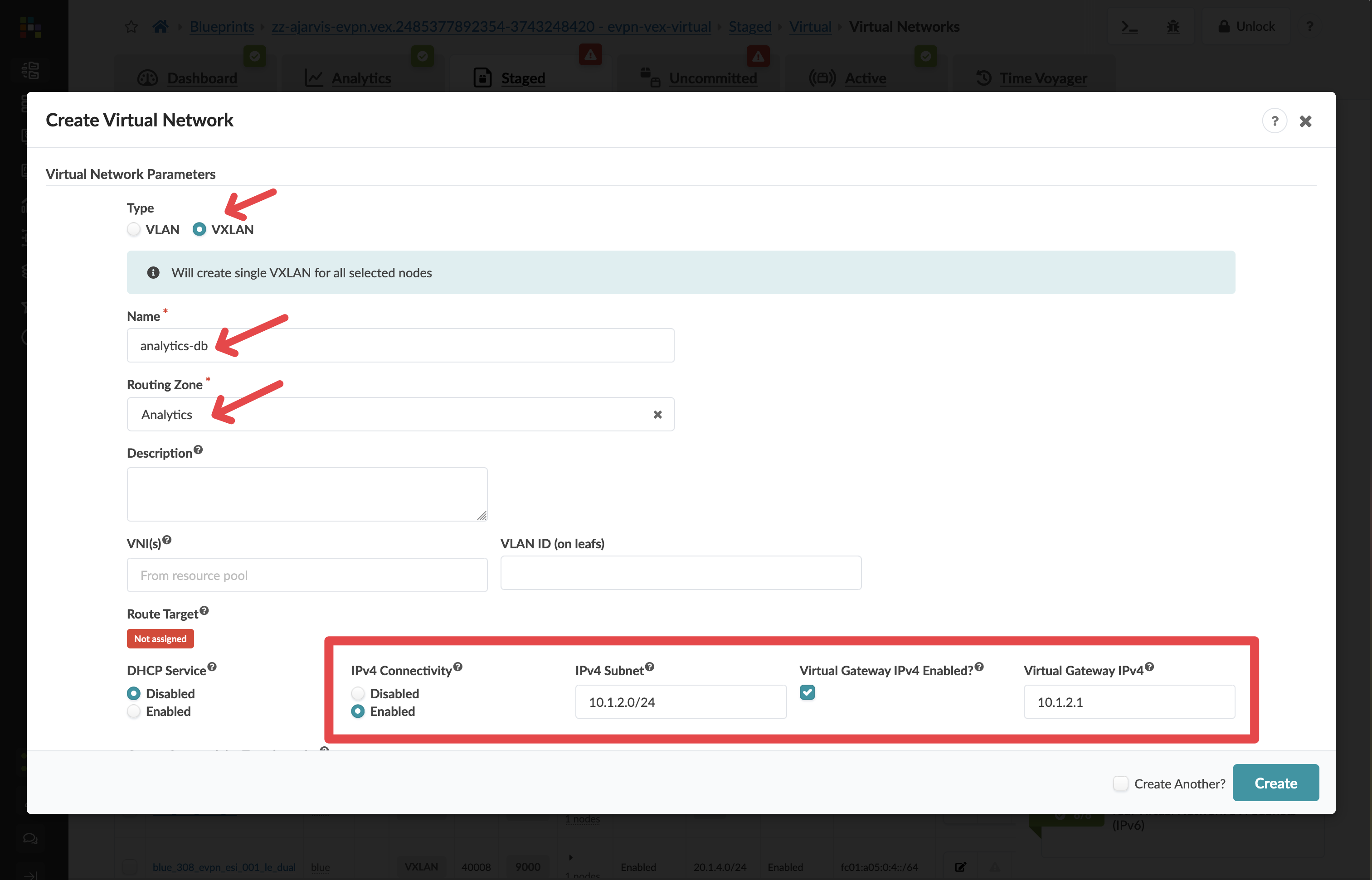
|
Why enable IPv4 Connectivity here? The database tier is internal — it does not need to pass through an external firewall. Enabling IPv4 Connectivity places the gateway (10.1.2.1) directly on the leaf switches, so database traffic routes efficiently within the fabric without leaving it. |
-
In Create Connectivity Templates for, select Tagged.
-
In Assigned To, select all racks.
-
Click Create.
Assigning resource pools
After creating the virtual networks, Apstra will identify that the Analytics routing zone now needs loopback IP addresses — one per switch — to function correctly in the fabric. These are allocated from IP address pools that were configured when Apstra was set up.
You will see red resource indicators on the routing zone. This is expected.
-
Click the red indicator and assign any available pool from the list.
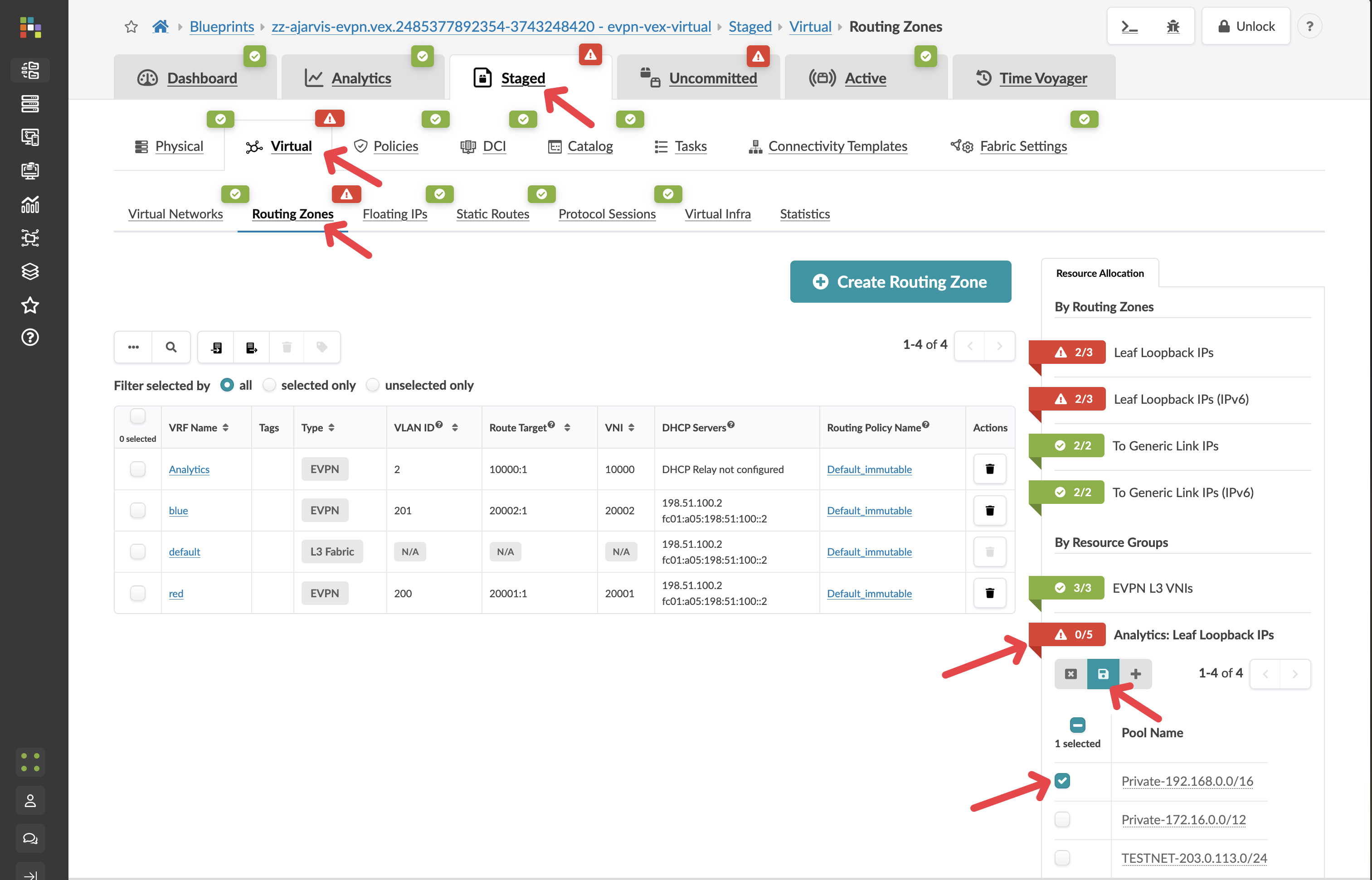
Apstra will allocate individual IP addresses from that pool to each switch automatically — you are just pointing it at the right pool to draw from.
|
You can create your own IP pools. in apstra. Or if you really wanted to you could statically assign an IP address manually for each Loop back IP on every switch. But the beauty of this is that you can just say "here’s a pool of addresses, use them as needed" and Apstra will take care of the rest. This is a great example of how Apstra abstracts away low-level details and lets you work at a higher level of intent. |
Verify the incremental configuration
-
Navigate to menu:Staged[Physical > Topology]
-
Select a leaf switch and click the Incremental Configuration tab again.
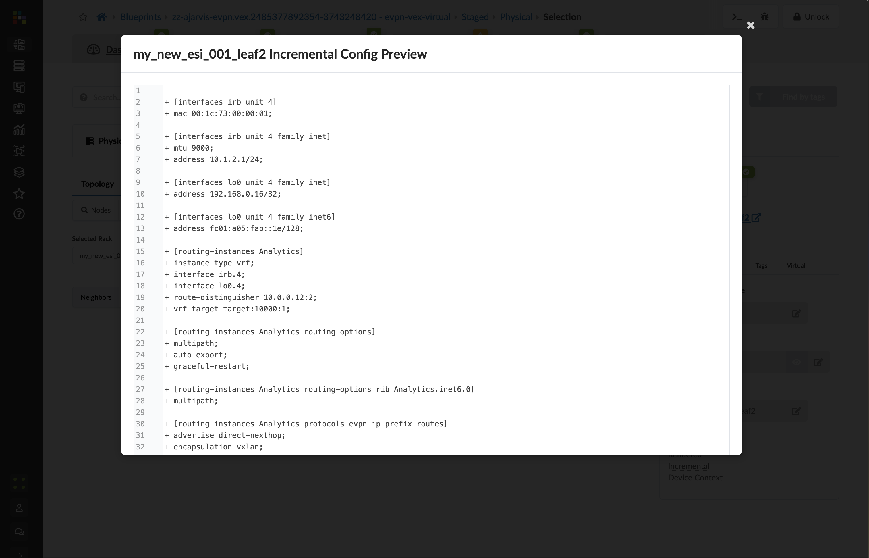
Compare this to the empty tab you saw earlier. Apstra has now generated VXLAN VNI mappings, VRF configuration, EVPN route-target policies, and interface assignments — all because you assigned two virtual networks to every rack. This is the configuration it will push to the switch when you commit.
-
Click the Uncommitted tab, enter a commit message such as Added Analytics virtual networks, and click Commit.