Lab Guide 1 - Juniper
Day 2 Operations: Expanding Data Centre Capacity
Scenario: Adding Capacity for the Big Data Analytics Service
Your company has just greenlit a new Big Data Analytics service offering for customers. The first task is to expand the physical capacity of your data centre by adding a new rack of switches and servers to support the increased compute requirements.
Task: Add a New Rack to Your Data Centre
|
Reflection Point: Before we begin, take a moment to consider what this would involve in a traditional data centre:
Many organisations report this process taking days or even weeks for a single rack addition when done manually. |
With Apstra, we’ll accomplish this in just a few minutes. Let’s begin!
Step 1: Navigate to the SE Demo Blueprint
-
From the Apstra main menu, select Blueprints
-
Click on the SE Demo blueprint to open it
Step 2: Add a New Rack to the Blueprint
The easiest and fastest way to expand your network is to add a rack:
-
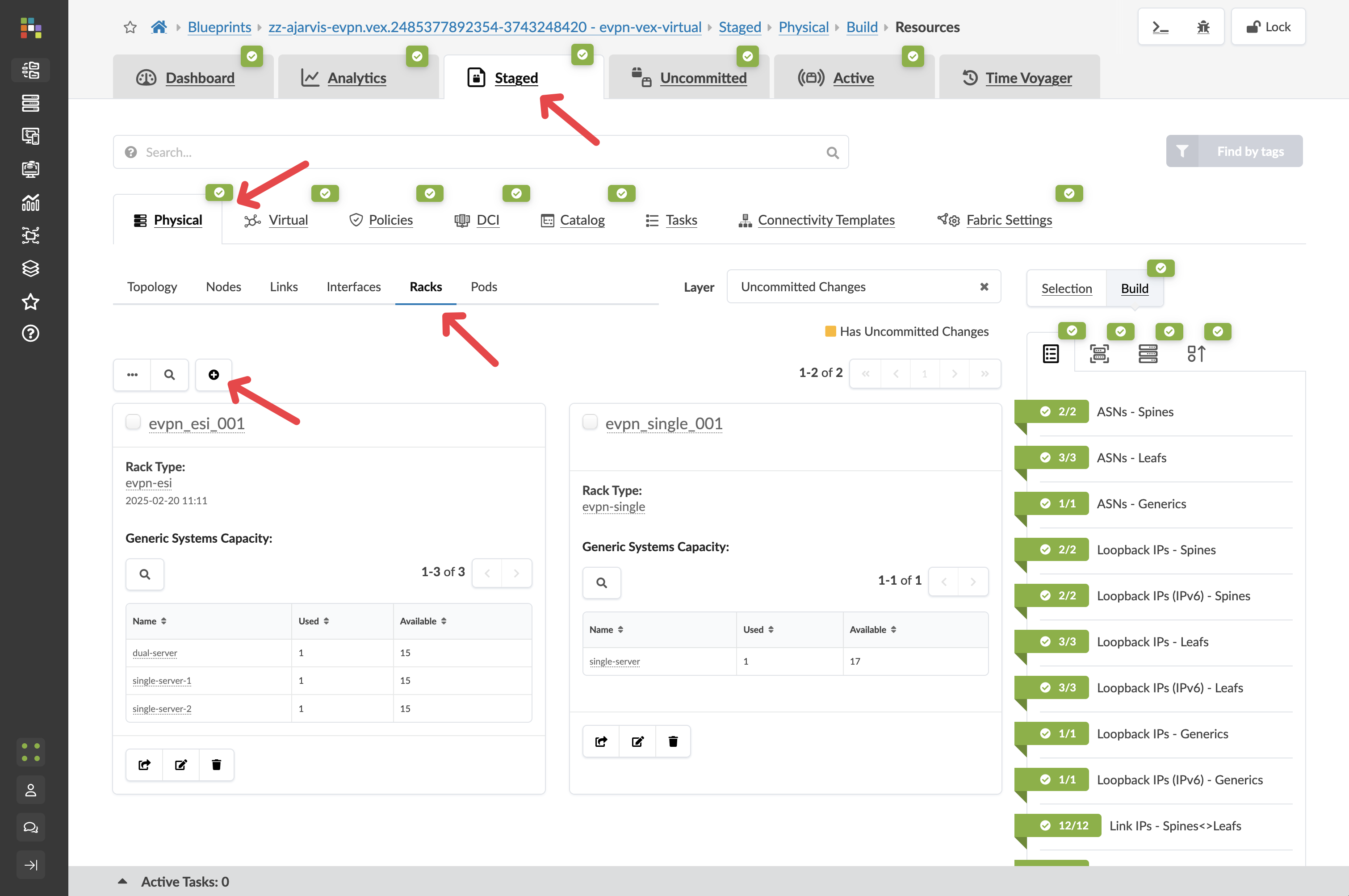
Navigate to
-
Click the Add Racks button (+)
-
From the Rack Type drop-down list, select your_name-esi (the dual-switch redundant rack with ESI that you designed in Part 1)
-
Leave the number of racks at 1
-
Click Add to stage the rack addition and return to the topology view
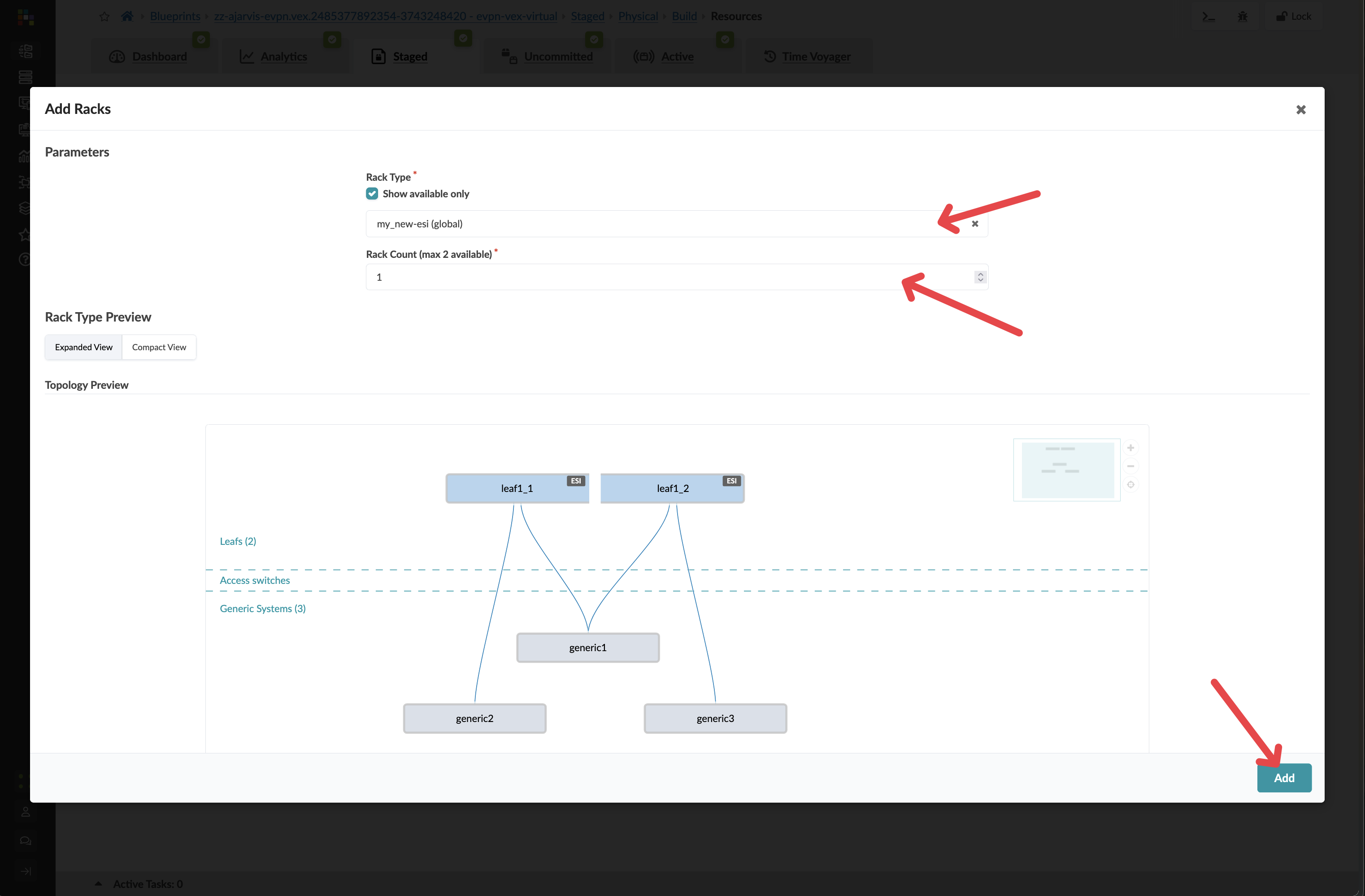
Key Insight: At this point, you’ve just prestaged a rack addition without needing any physical hardware. Apstra allows you to plan and prepare your network expansion before the physical switches even arrive in your data centre.
Step 3: Let Apstra Handle Resource Allocation
When you add a new rack, you will need to add new IPs and ASNs. Apstra does this for you, taking the next items from your resource pools.
You don’t need to do a thing, it does it for you
Step 4: Assign Device Profiles
-
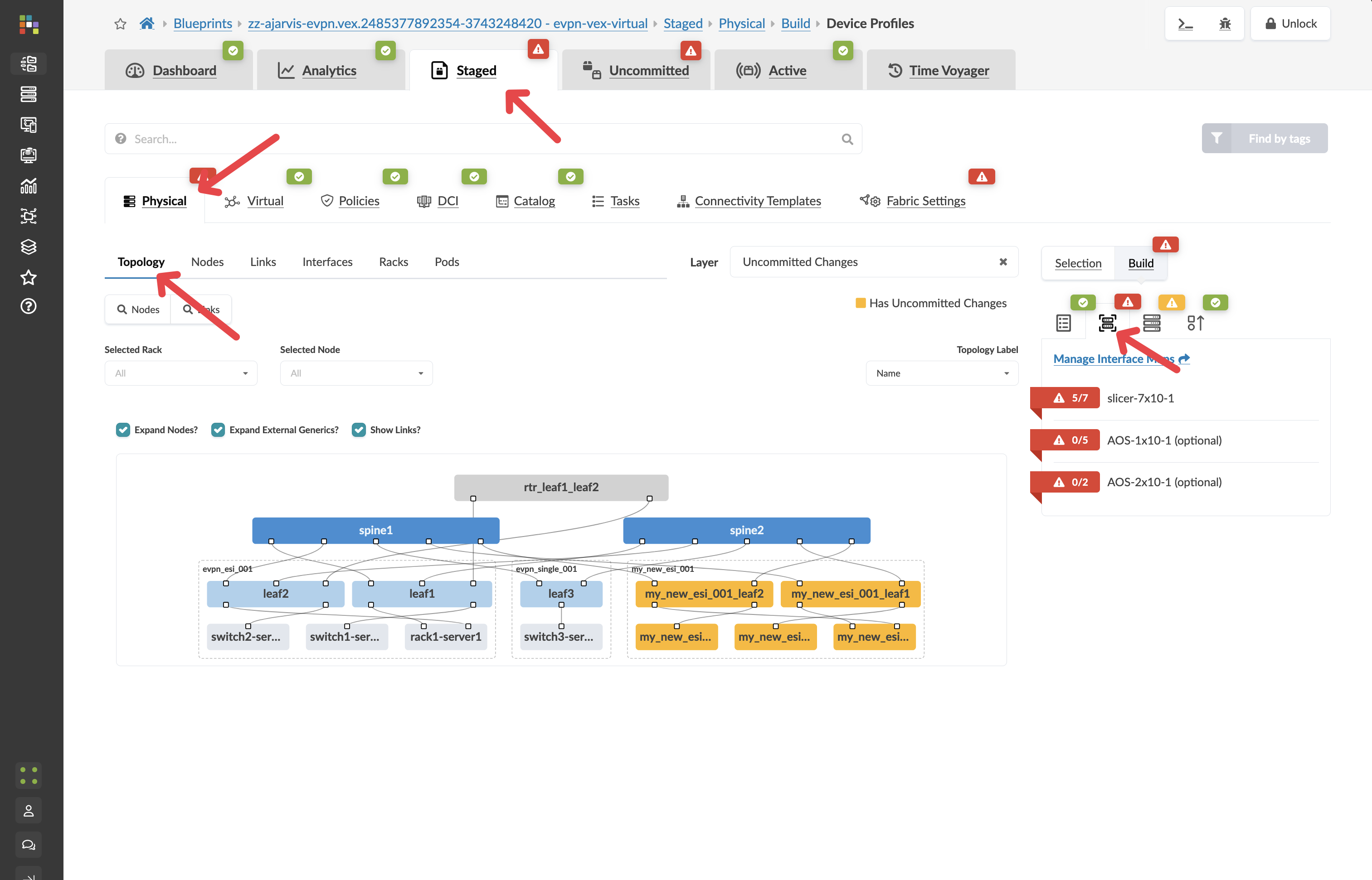
Navigate to
-
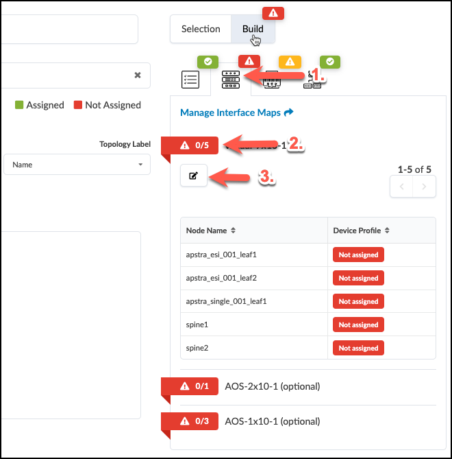
If there are any red indicators for your new leaf switches, click them, then click Change interface maps assignment
-
Select Juniper_vEX__slicer-7x10⁻¹ as the interface map for your new leaf switches, you were telling Apstra what the underlying devices will be.
-
Click Update Assignments
Step 5: Review and Commit Your Changes
-
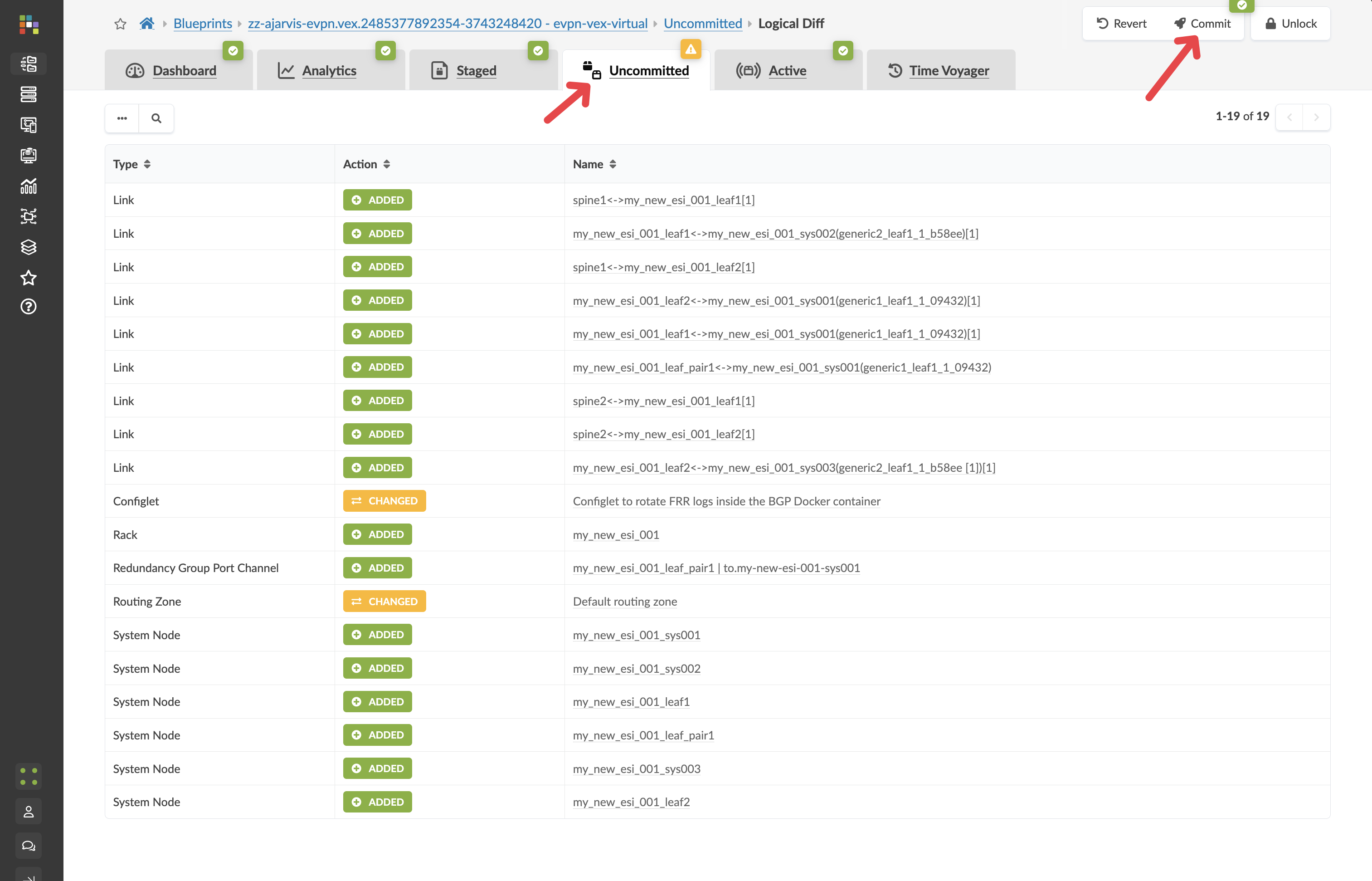
Click the Uncommitted tab to see all your staged changes
Take a moment to review what Apstra is preparing for you. Notice how the system has automatically:
-
Created a plan for assigning unique ASNs to the new devices
-
Prepared IP addressing for all interfaces
-
Set up BGP peering configurations between the new leaf switches and existing spine switches
-
Prepared EVPN configurations for the overlay network
-
-
After reviewing, enter a commit message like "Prestaged new analytics rack" and click Commit. Make sure to give it a meaningful description.
Step 6: Understanding the Power of Prestaging
What makes this workflow revolutionary is that:
-
No physical devices needed yet: You’ve prestaged the entire configuration before the physical switches even arrive at your data centre
-
Instant deployment when hardware arrives: When the physical switches do arrive, you simply:
-
Rack and cable the switches according to your design
-
Add the devices to Apstra’s management
-
Map them to the prestaged leaf switches in your blueprint
-
The full configuration will be pushed to them in seconds
-
-
Zero-touch integration: The new switches will be fully deployed, configured, and monitored as part of your fabric immediately
-
Network-wide consistency: All existing devices that need to communicate with these new switches will be automatically updated to include them in the fabric
Step 7: Examine the Prepared Configuration
Let’s look at what Apstra has prepared:
-
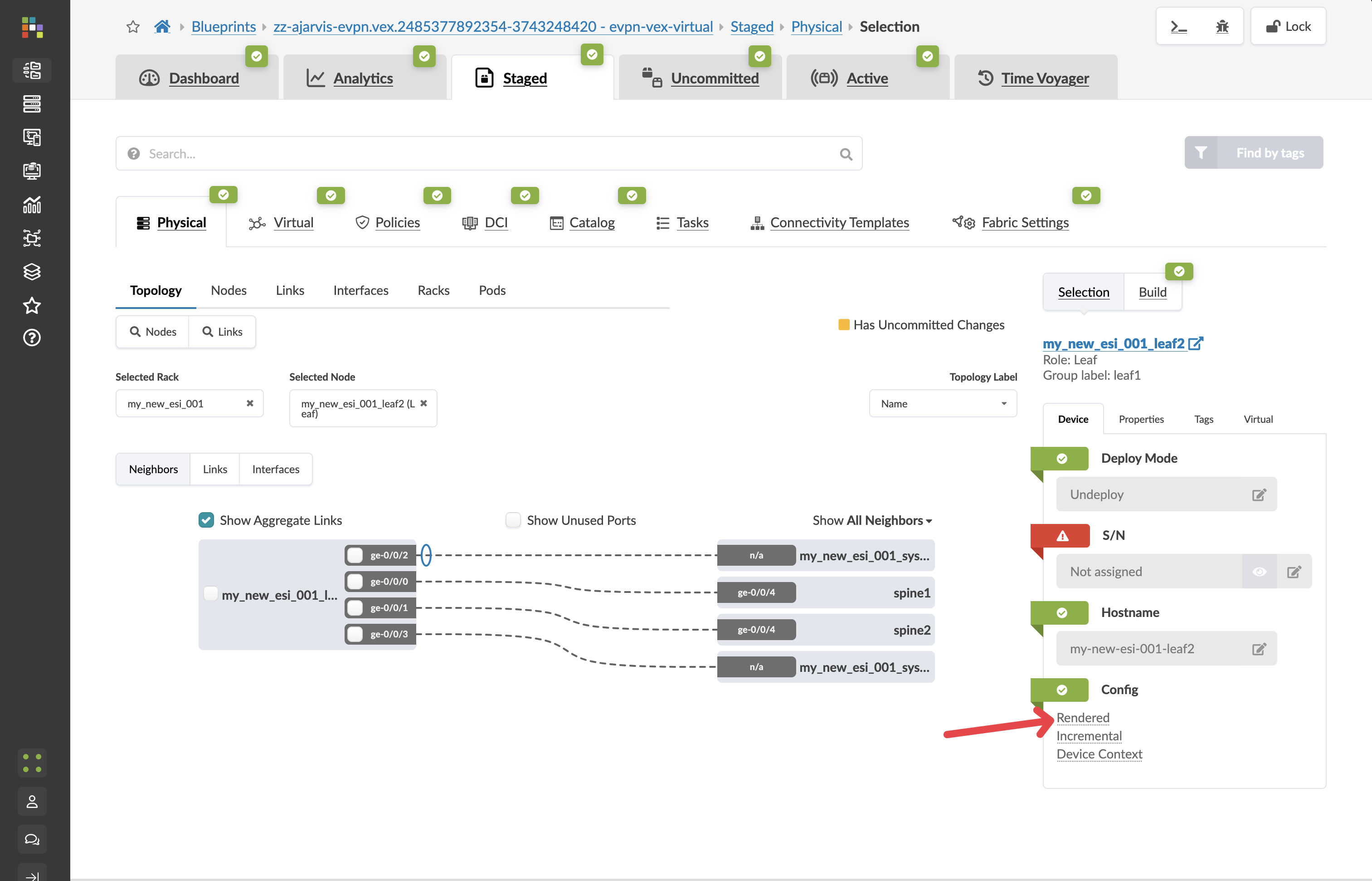
Navigate to
-
Find one of your newly added leaf switches and click on it
-
Click on the Rendered Configuration tab
-
Review the complete configuration that Apstra has generated. Notice:
-
Basic system configuration
-
Interface configurations
-
BGP underlay configuration
-
EVPN overlay configuration
-
All IP addressing
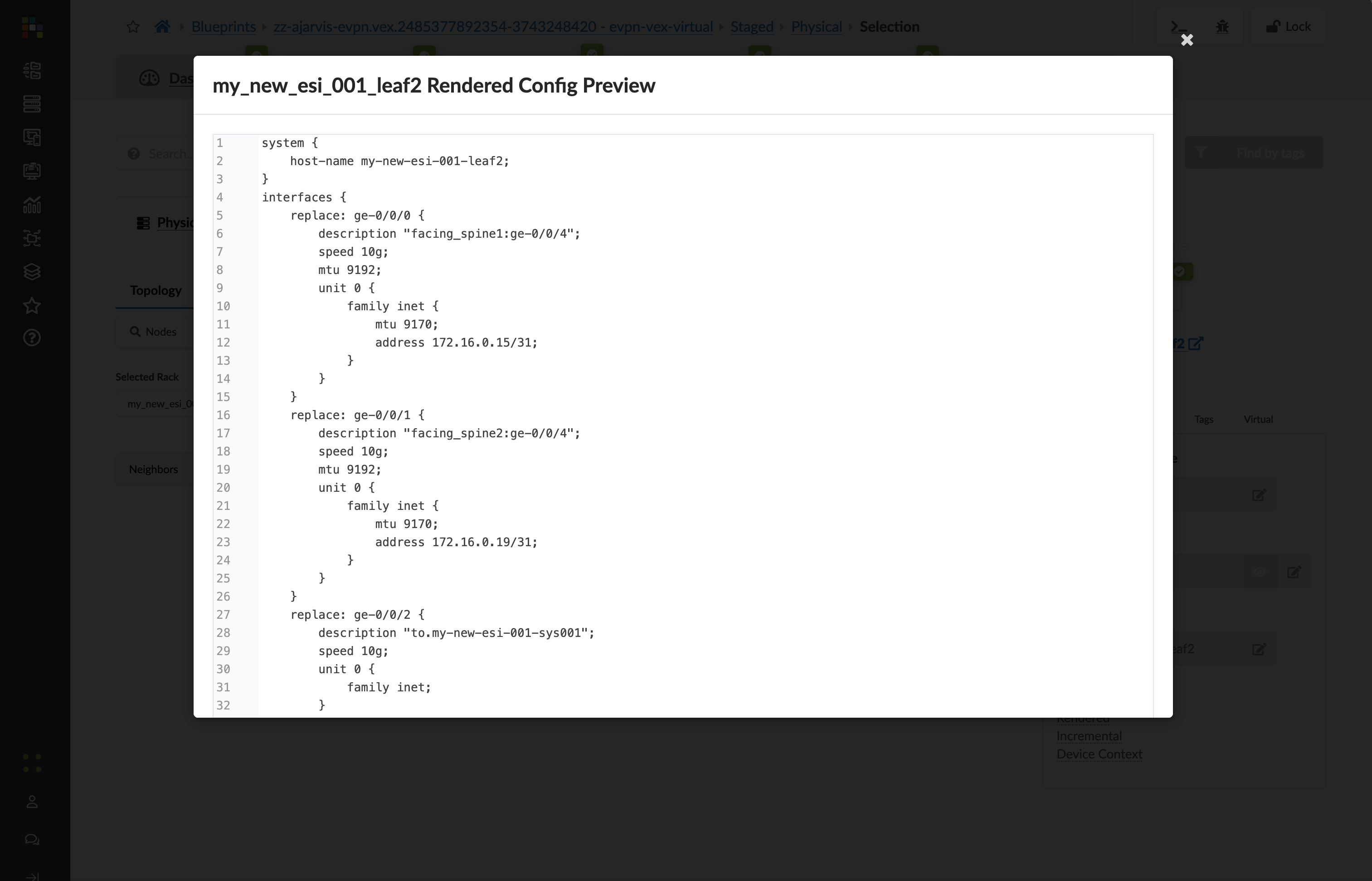
This entire configuration was generated automatically because Apstra understands your network as a complete system. When the physical devices are added, this configuration will be deployed to them, and the system will also automatically update configurations on the spine switches to establish BGP sessions with these new devices.
-
What You’ve Accomplished
In just a few minutes, you’ve:
-
Prestaged a new rack with redundant leaf switches to your data centre
-
Created a plan for all necessary resources (ASNs, IP addresses)
-
Generated complete device configurations that will be ready when the hardware arrives
-
Prepared updates for existing devices to incorporate the new rack into the fabric
In a traditional networking environment, this entire process would require extensive planning, manual configuration, and troubleshooting once the hardware arrives. With Apstra, you can prepare everything in advance and deploy instantly when hardware is available.
Next, we’ll continue expanding our Big Data Analytics service by creating a new routing zone to logically separate this service from other workloads.