Lab Guide 1 - Juniper
Day 2 Operations: Setting Up External Connectivity
Scenario: Enabling External Access to the Analytics Service
The final step in deploying our Big Data Analytics service is to set up external connectivity. Customers need to access the analytics platform from outside our data centre, which requires setting up BGP peering with an external router or firewall. Additionally, we need to ensure our Layer 2 web tier has its gateway on an external firewall for enhanced security.
In this task, we’ll create an external router and configure BGP peering to connect our Analytics routing zone to the outside world.
Task: Configure External Connectivity for the Analytics Service
|
Reflection Point: In traditional networking, setting up external connectivity would involve:
This process is complex and error-prone, with serious consequences if misconfigured. |
Let’s see how Apstra simplifies this mission-critical task!
Step 1: Add an External Generic System
First, we’ll create an external device to represent our edge router or firewall:
-
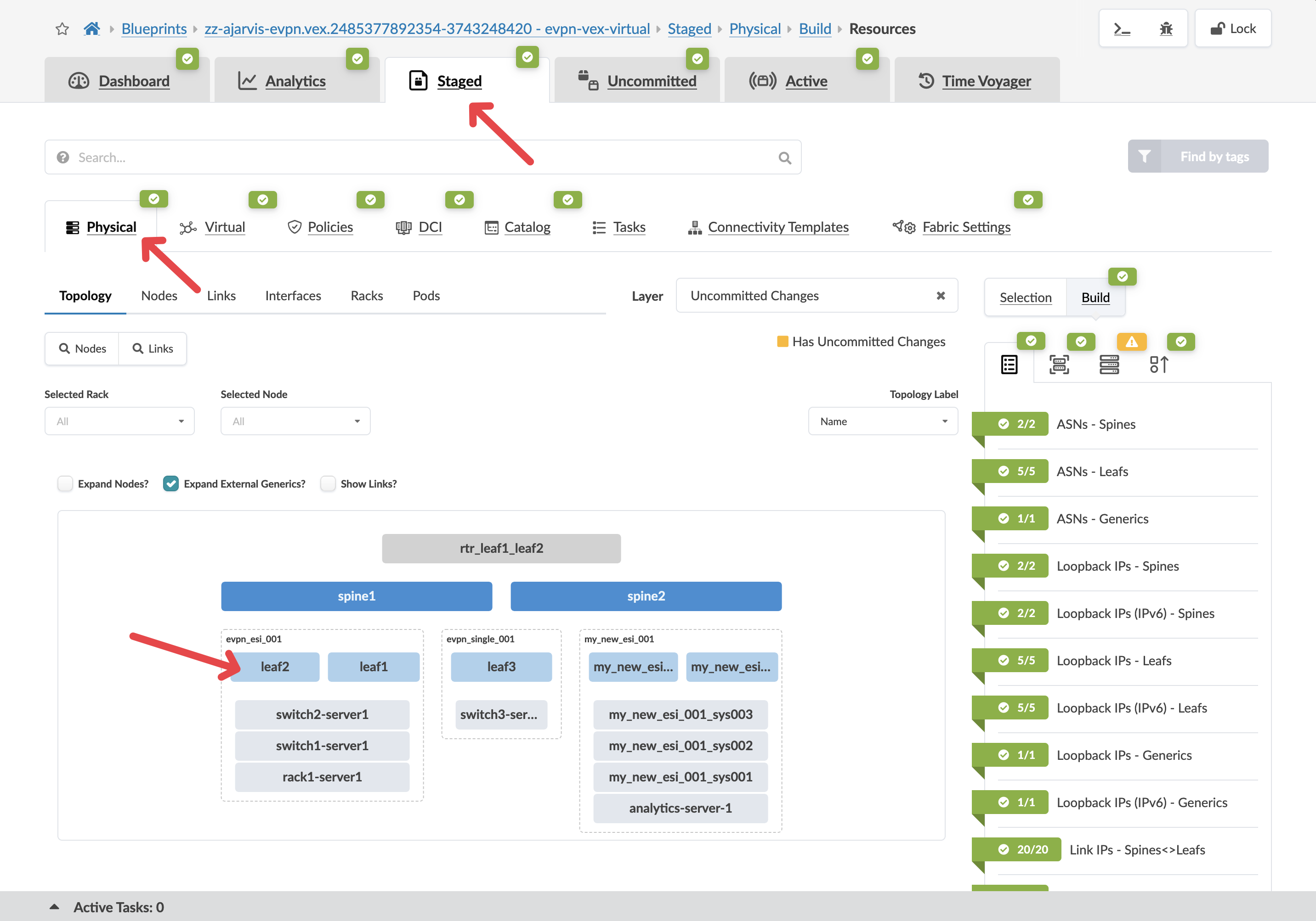
Navigate to
-
Select a border leaf switch that will connect to the external world
-
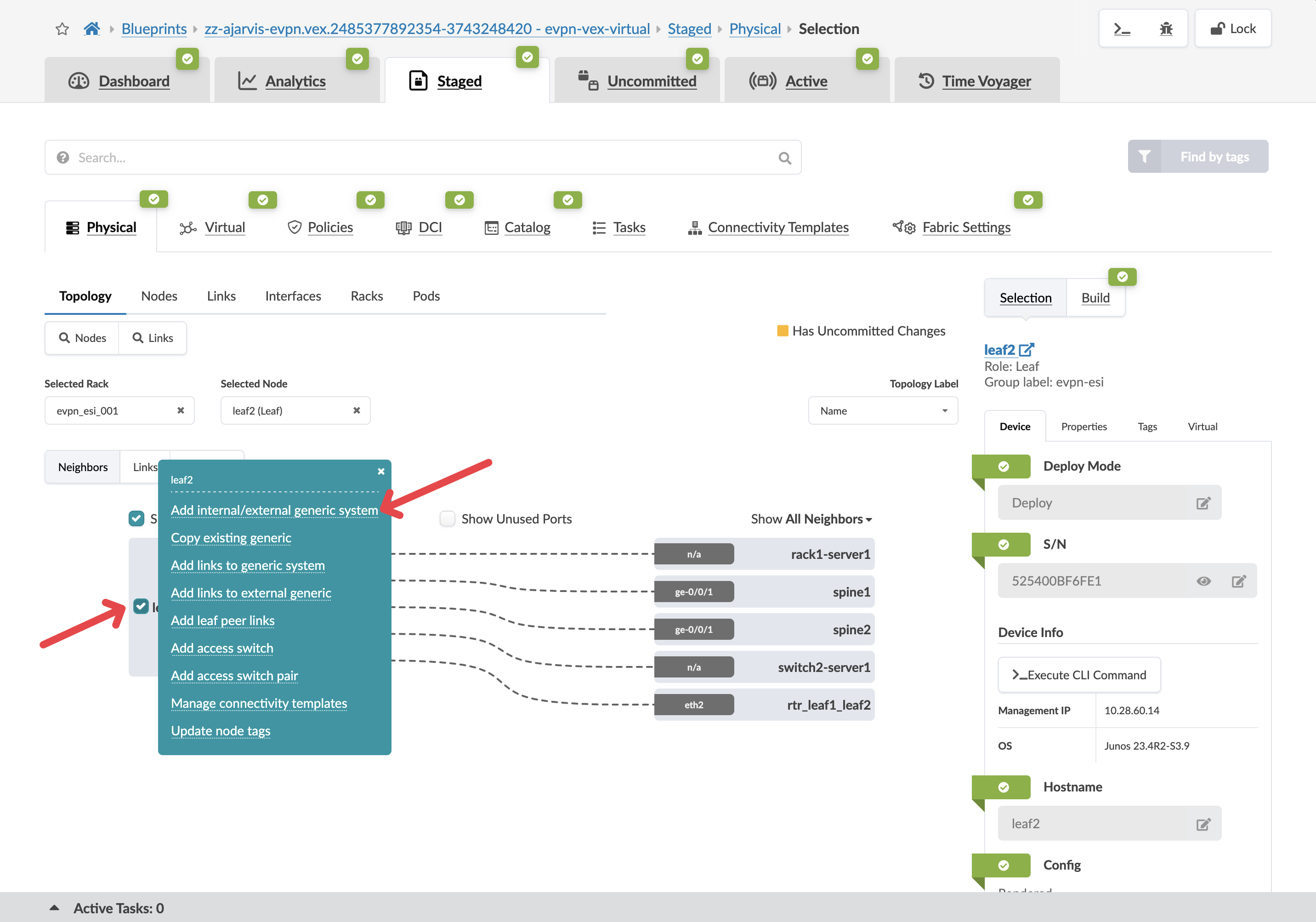
With the switch selected, click the box to the left of the device’s name
-
From the menu, select Add internal/external generic system
-
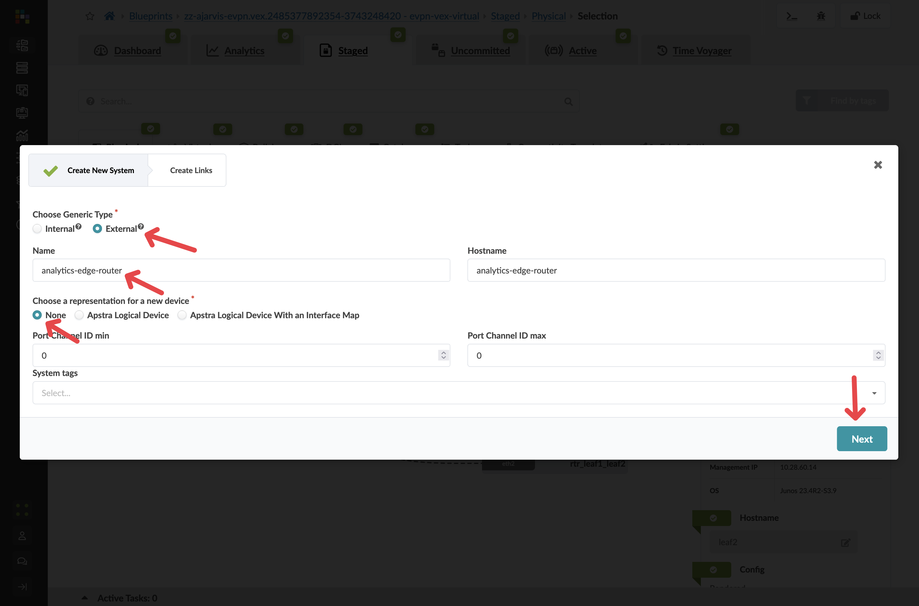
Configure the external system:
Parameter Value Generic Type
External
Name
analytics-edge-router
Hostname
analytics-edge-router
Logical Device
None
|
Why External Generic System? We’re using an external generic system because this device lives outside of our typical rack structure and represents equipment external to the data centre that provides connectivity to the outside world. In this case, it will also serve as the Layer 3 gateway for our analytics-web virtual network. |
-
Click Next to configure the links
Step 2: Configure the External Links
-
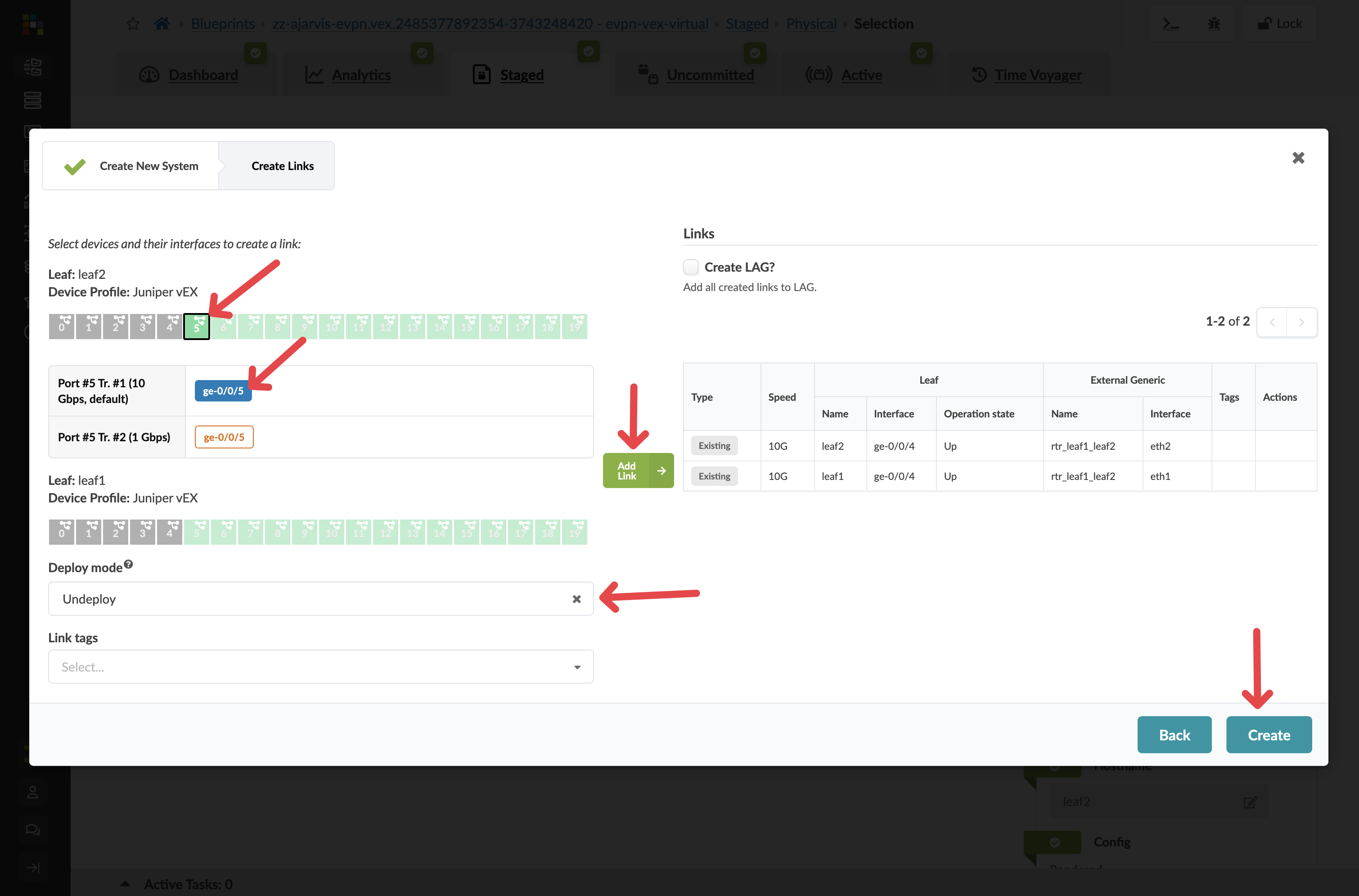
For the selected leaf2 switch:
-
Choose an available port (e.g., port 5)
-
Set speed to 10Gbps
-
Set Deploy mode to Undeploy
-
We don’t actually have this firewall yet but we are just staging the peering for when it is installed and we then set this external generic system to deployed
-
-
Add a tag: Router
-
-
Click Add Link to add this connection
-
If you want redundancy (recommended), repeat for a second border leaf:
-
Choose a corresponding port
-
Set the same parameters
-
Add the same tag
-
-
Click Create to add the external router
Step 3: Configure External Router Properties
Before creating the connectivity template, we need to configure the ASN and loopback IP for our external router:
-
Click on your analytics-edge-router
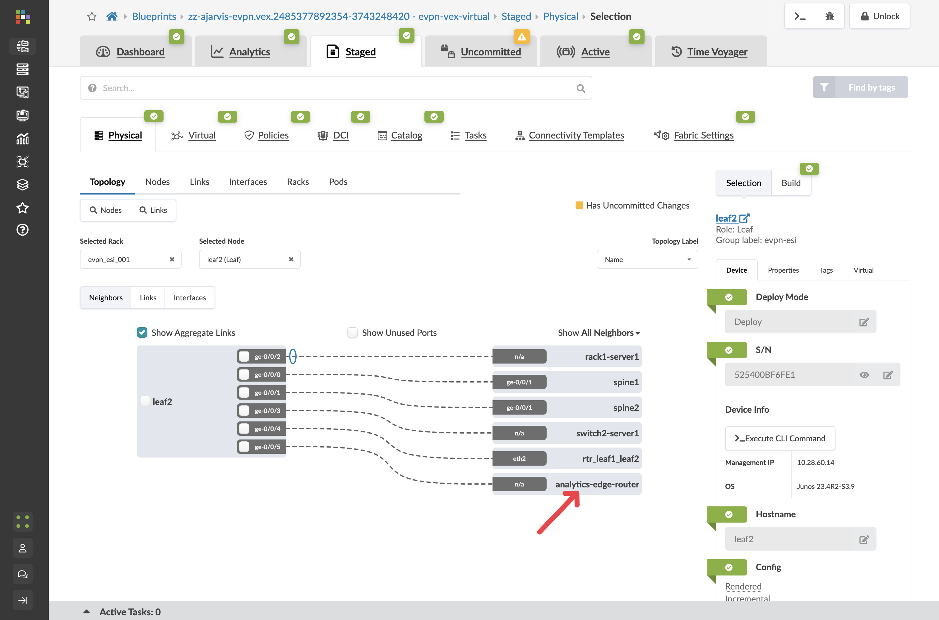
-
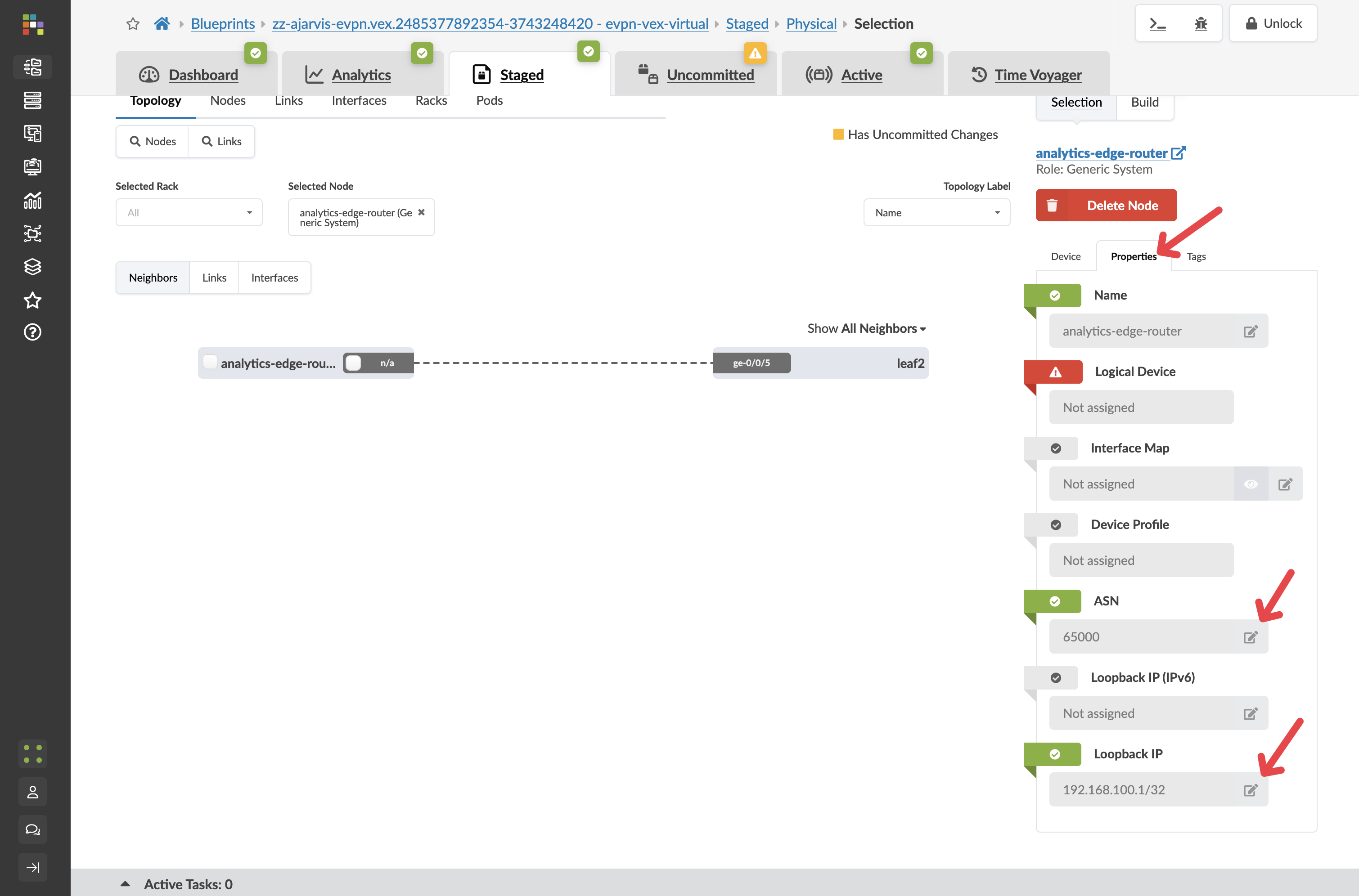
Click the Properties tab
-
Configure the ASN and loopback IP:
Parameter Value ASN
65000 (or another appropriate external ASN)
Loopback IP
192.168.100.1/32 (or another appropriate IP)
-
Click the Edit icon for each field and save your changes
|
These values are essential for the BGP peering relationship between your fabric and the external router. The ASN must be different from the ASNs used within your fabric. |
Step 4: Create Connectivity Using a Predefined Template
Think of Connectivity Templates as your way of expressing network connectivity intent rather than just mapping interfaces to VLANs. While traditional networking has you manually configuring individual switch ports with VLANs/VXLANs, Apstra’s Connectivity Templates create a higher-level abstraction that defines 'the way things connect' to your network.
Yes, at first glance, it might seem more complex than simply typing 'switchport access vlan 100' on an interface. But what Connectivity Templates give you is immensely more powerful:
-
Consistency across your fabric: Define the connectivity pattern once, apply it consistently everywhere.
-
Multi-faceted connections: It’s not just about mapping to a single VLAN. Templates can include multiple parameters static routes, BGP peerings, constraints, etc.
-
Intent-based approach: You’re expressing what you want to achieve (connect this server to this virtual network) rather than how to configure it on specific hardware.
-
Automated implementation: The template knows how to implement itself across different switch vendors and models.
-
Reusability: Create the template once, use it for all similar connections.
For example, when we assigned our 'analytics-web' template to server interfaces, Apstra automatically configured the appropriate VLANs, VXLAN mappings, and trunk settings across redundant switches. If we had dozens of similar servers to connect, we’d apply the same template in seconds rather than configuring each port manually. It’s like the difference between writing configuration commands for every port versus declaring 'these servers belong to the web tier' and letting the system handle the details.
Now we’ll use a predefined connectivity template type to set up the connection between our fabric and the external router:
-
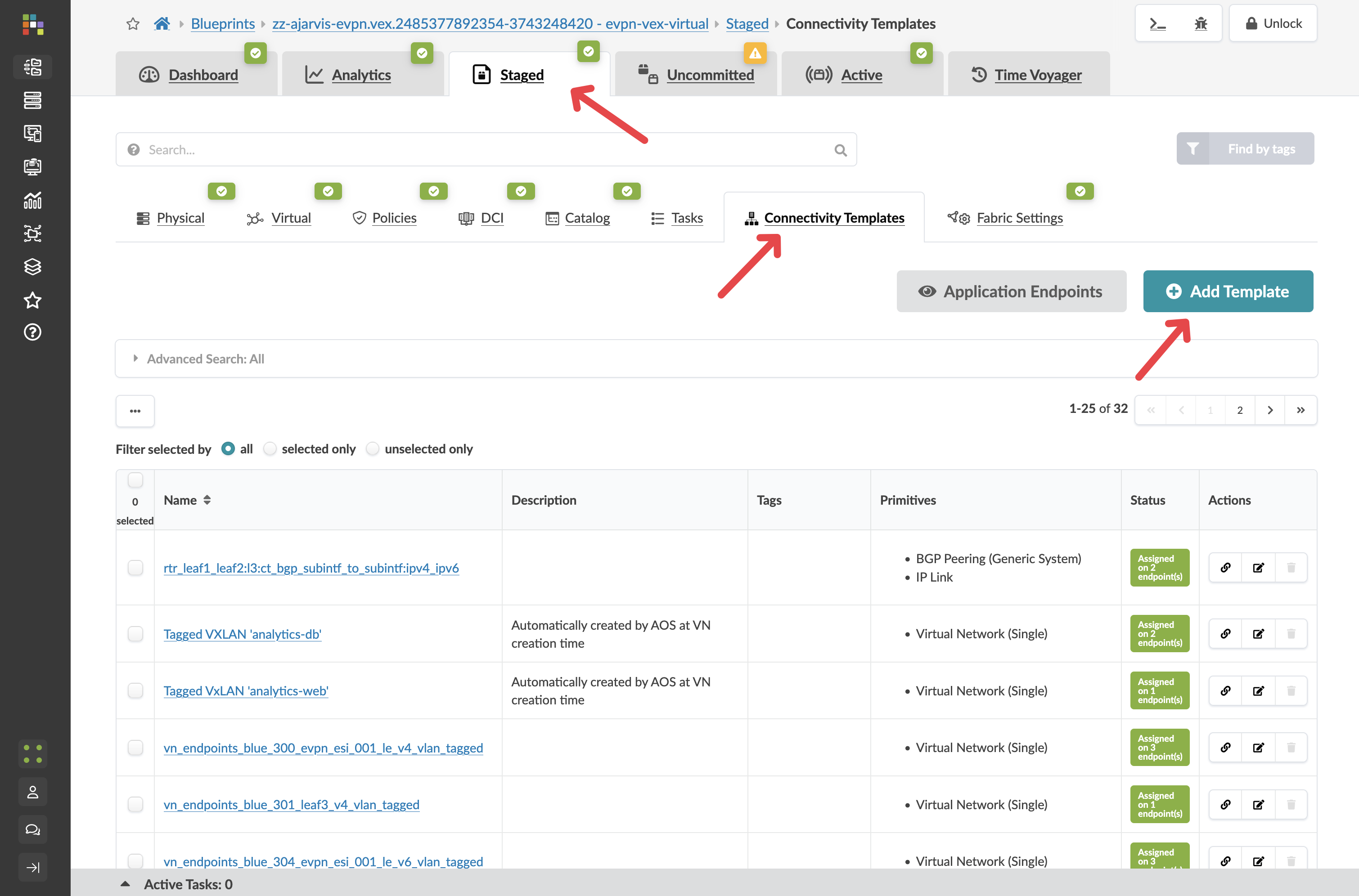
Navigate to
-
Click Add Template
-
Give your connectivity template the title

-
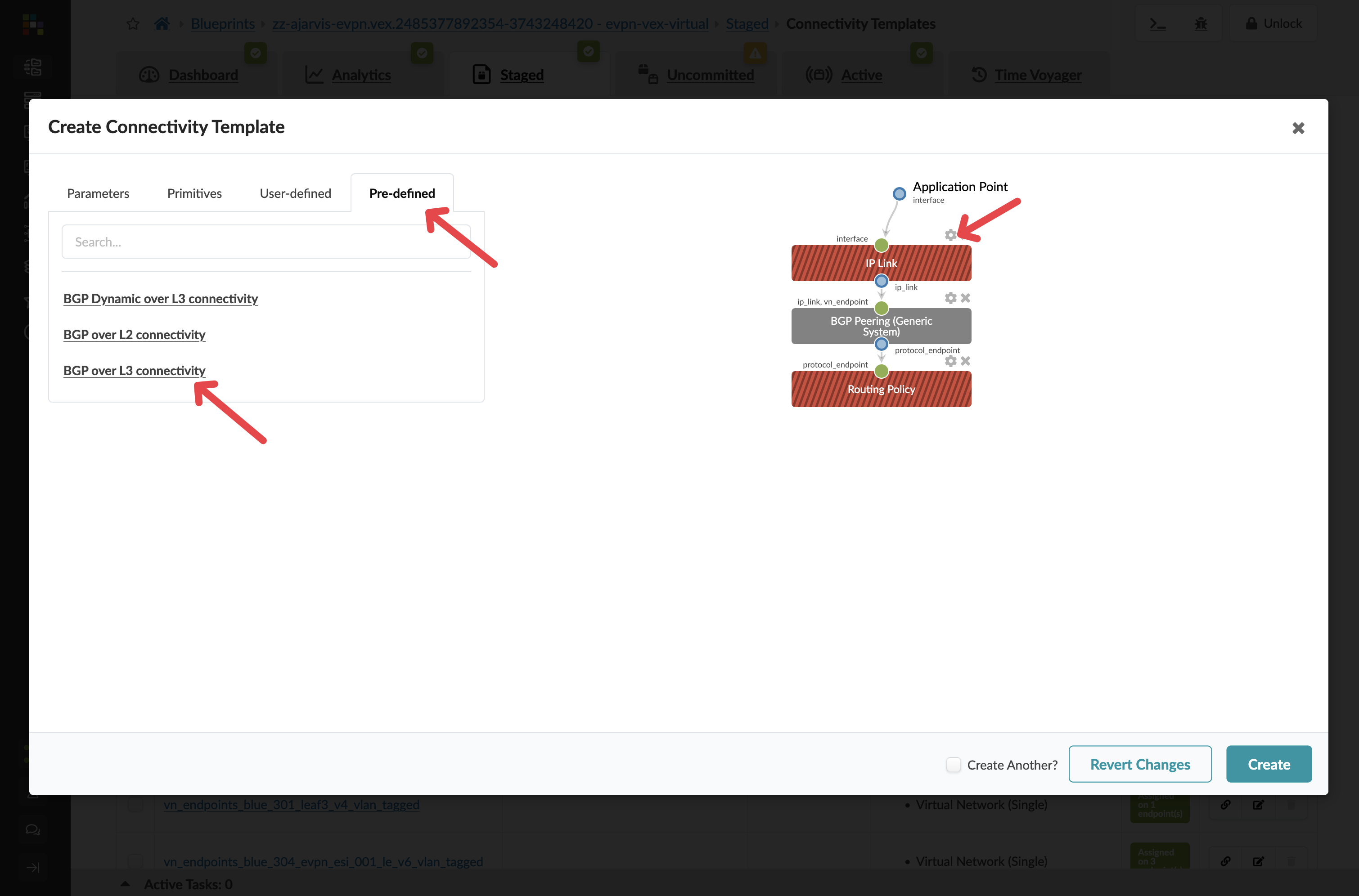
In the dialog, click the Predefined Templates tab
-
Select BGP over L3 Connectivity from the list of predefined templates
-
Select the cog next to the IP Link box
Parameter Value Title
analytics-external-peering
-
Configure the IP link settings
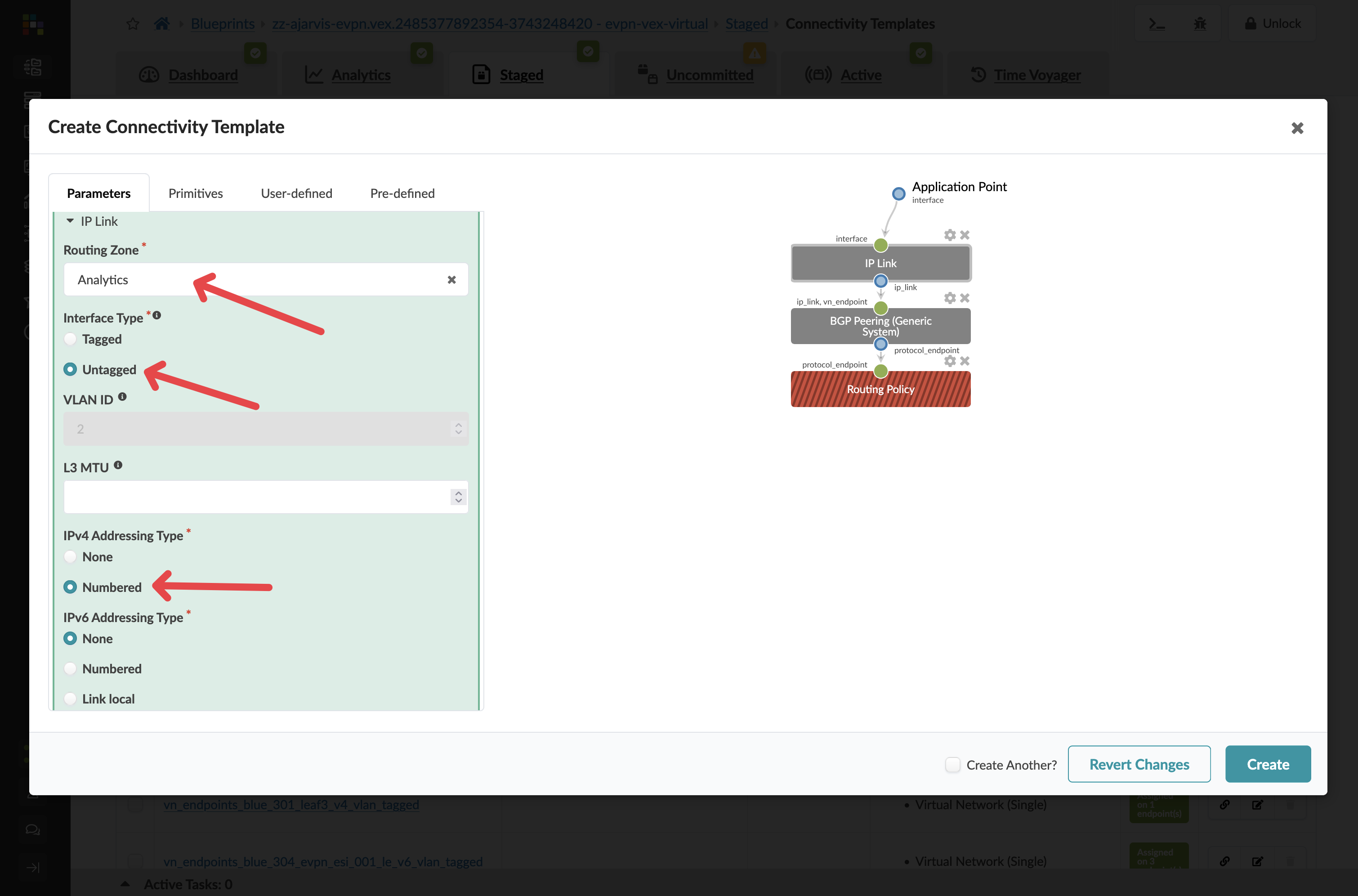
Parameter Value Virtual Network
analytics-web
Interface Type
Untagged
IPv4 Addressing Type
Numbered
|
Key Point: We’re connecting to the analytics-web virtual network because we want this external router to serve as the gateway for our web tier, as discussed earlier when we created the Layer 2 only network. |
-
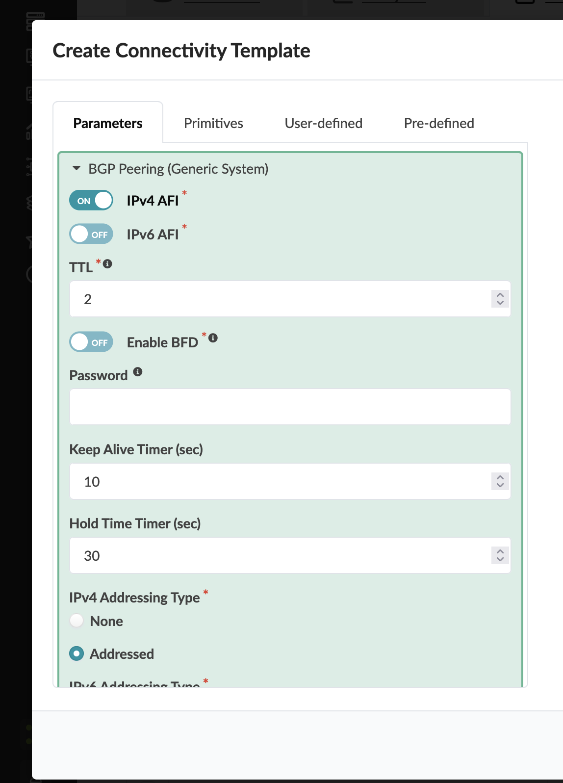
For the BGP Peering section, you can leave the default settings as they are. The external generic system’s ASN and loopback IP that we configured earlier are all that’s needed for the peering relationship.
-
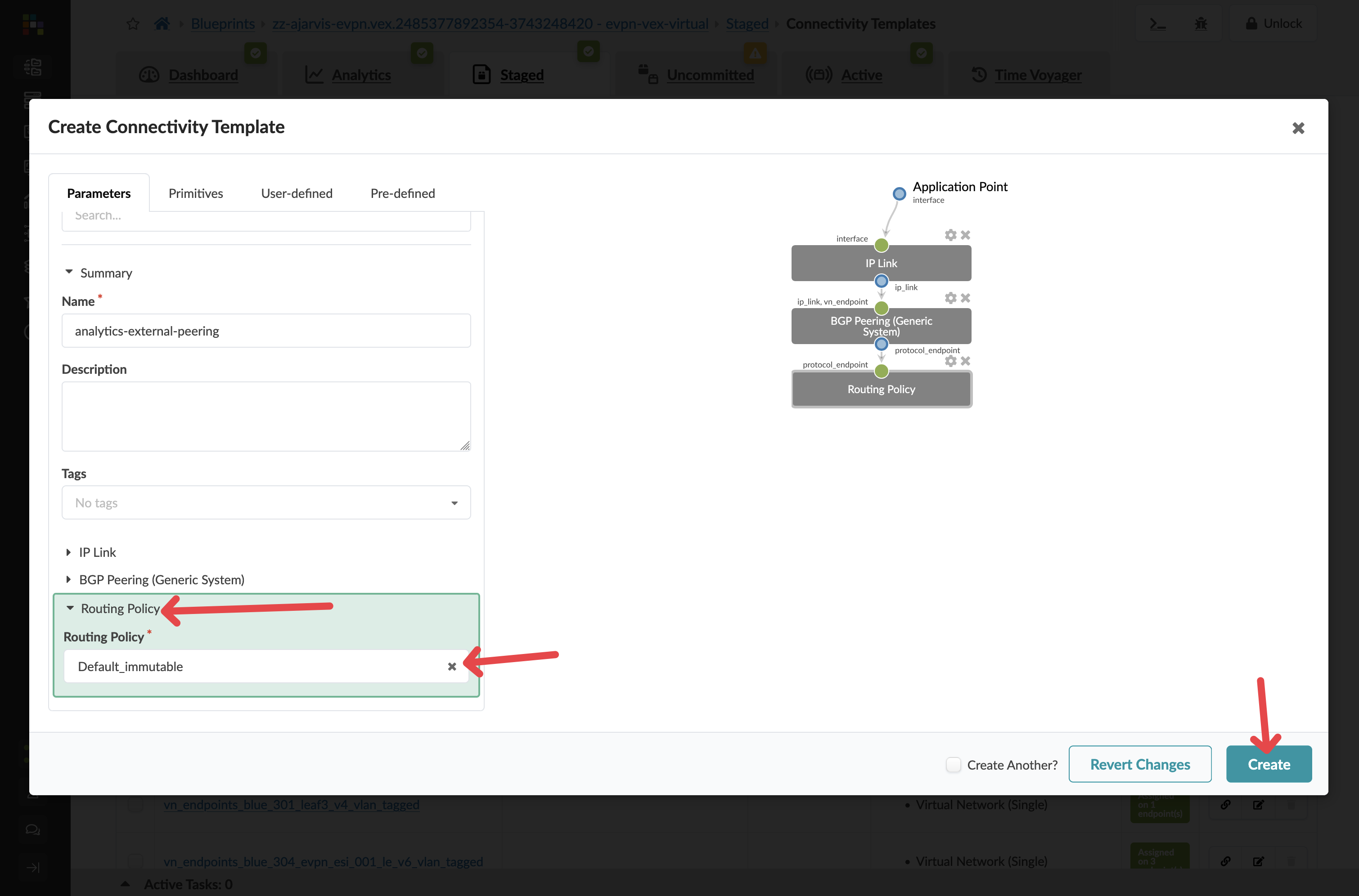
For the Routing Policy section, this is completely optional:
-
You can delete it
-
You can select Default Immutable Policy (which ships with Apstra)
-
You could create a custom routing policy if you wanted different constraints and control for this particular BGP peering compared to the rest of the VRF
-
|
Flexibility Note: The ability to specify different routing policies for different BGP peers gives you fine-grained control over routing behaviour when needed. |
-
Click Create to create the template
Step 5: Assign the Connectivity Template
-
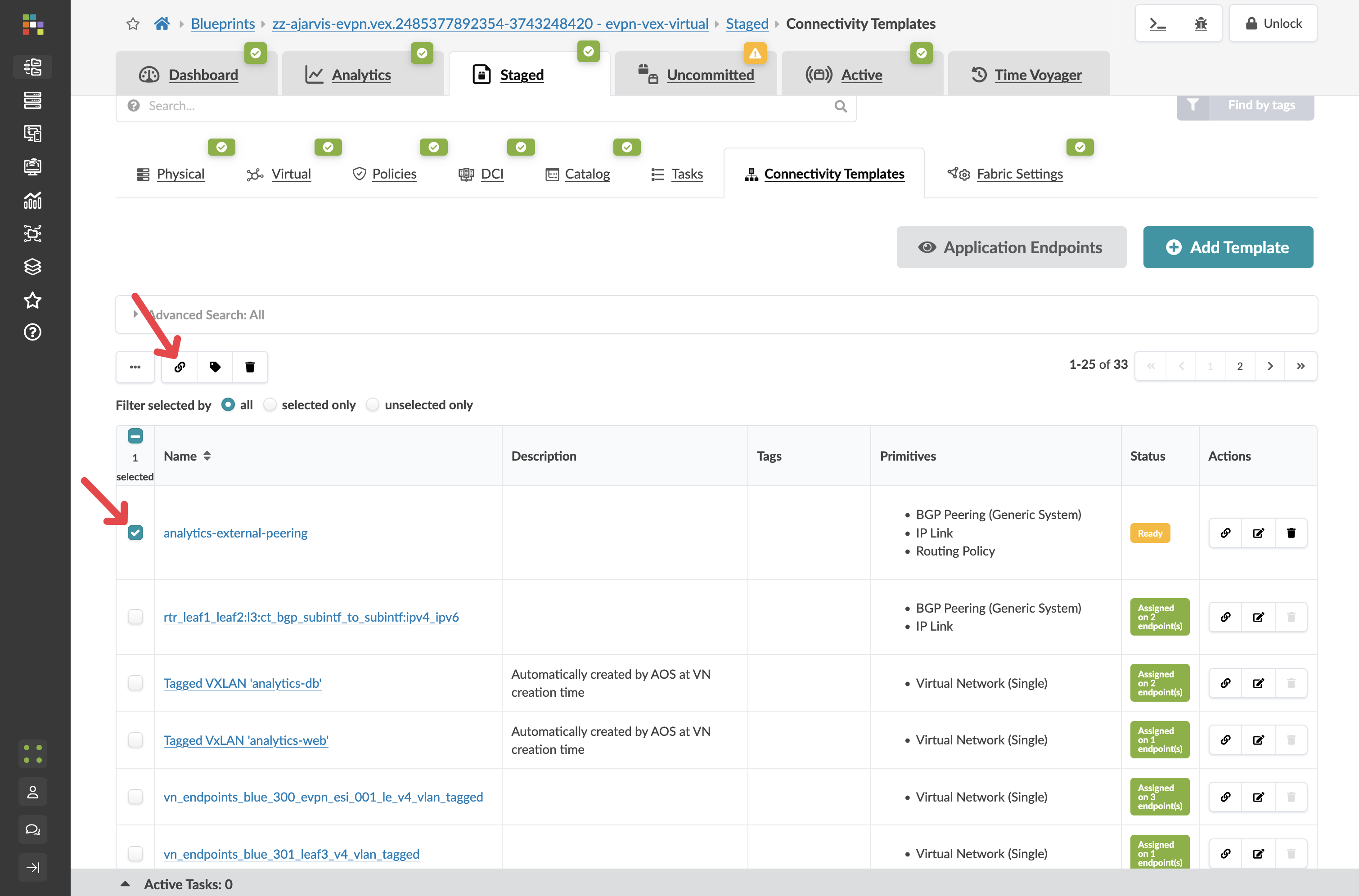
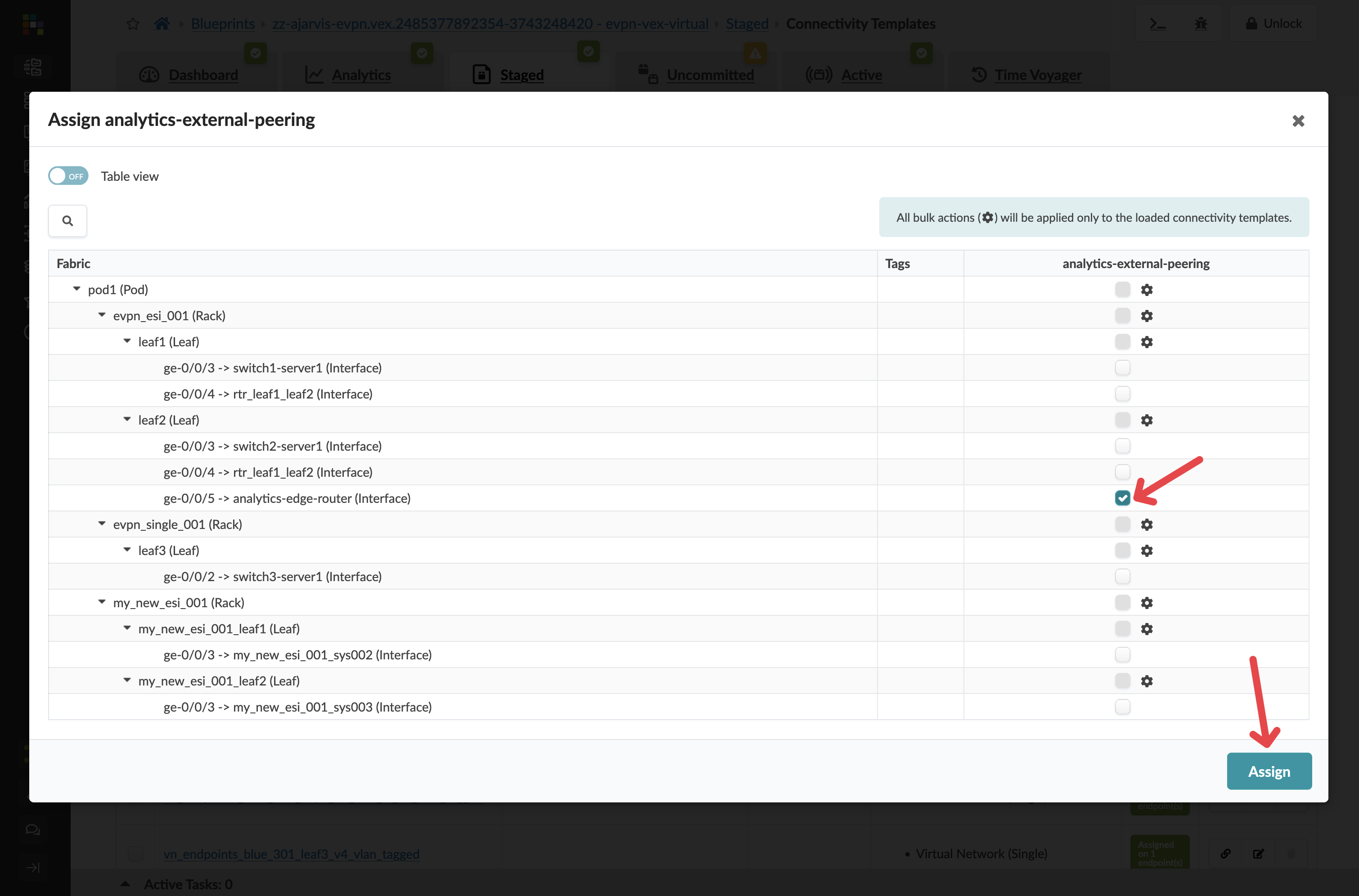
Find and select your new analytics-external-peering template in the list
-
Click the Assign icon
-
Check the boxes next to the interfaces connected to your external router
-
Click Assign
Step 6: Assign Resources for External Peering
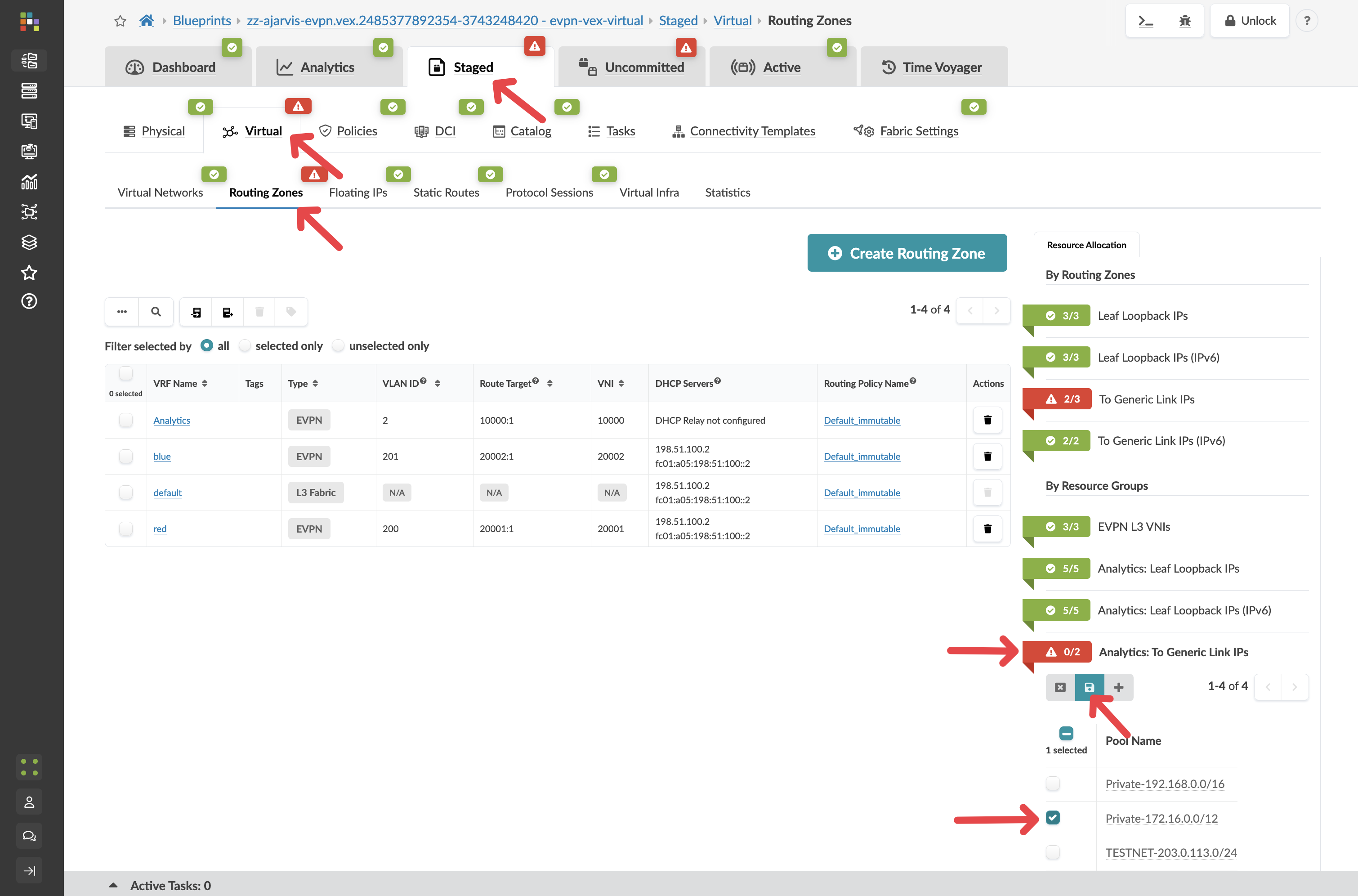
You will need to assign IP resources for the external peering:
-
Navigate to
-
Look for any red indicators related to your external connectivity
-
Assign appropriate resource pools as needed
|
Note: You can also assign these IP’s manually, you do not need to use a pool of addresses |
Step 7: Review and Commit Your Changes
Before you commit on your blueprint, let’s examine how Apstra has automated the complete configuration of your devices:
-
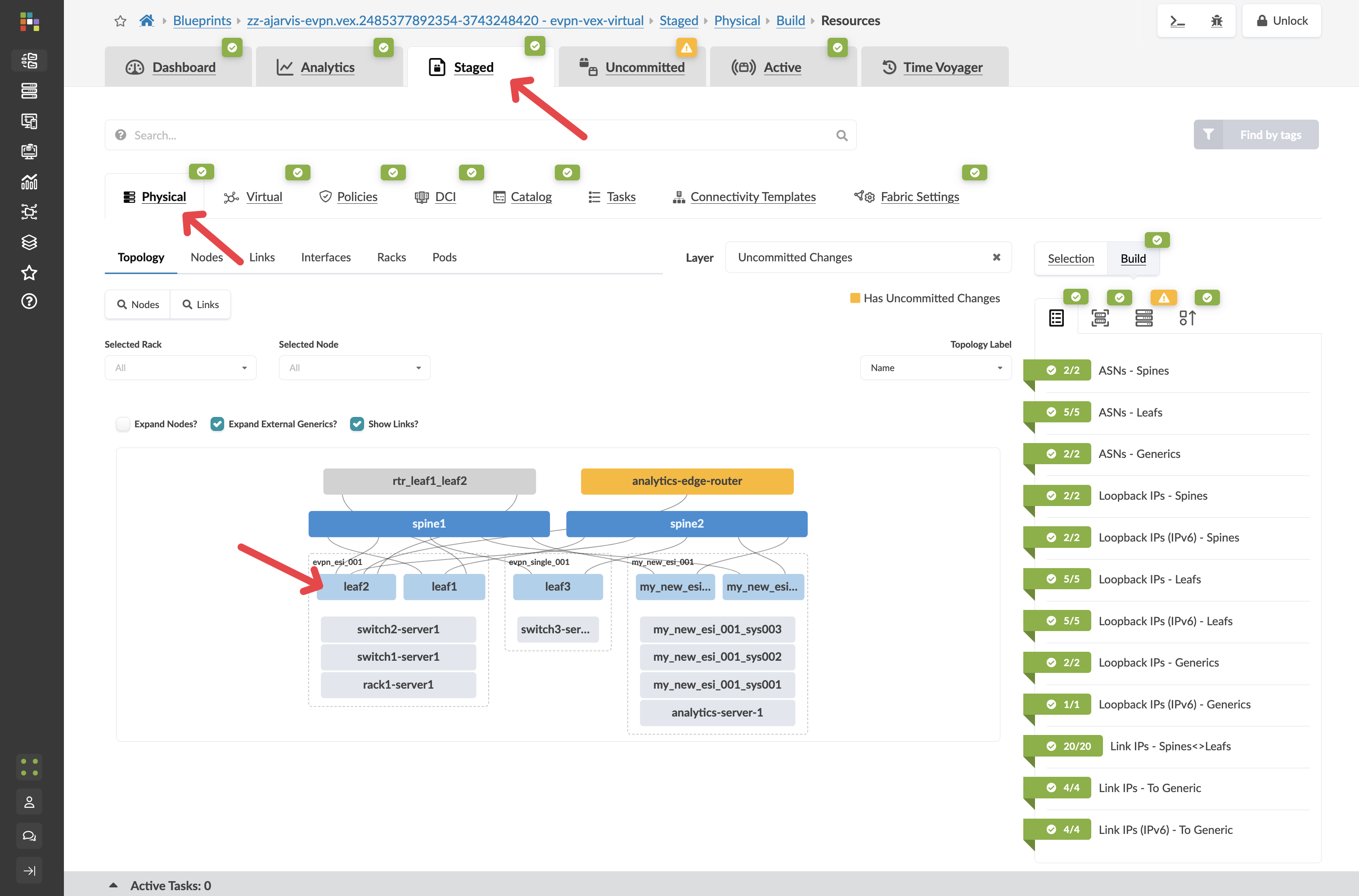
Navigate to Staged > Physical > Devices
-
Select one of your leaf switches by clicking on it
-
Click on the Incrimental Configuration tab
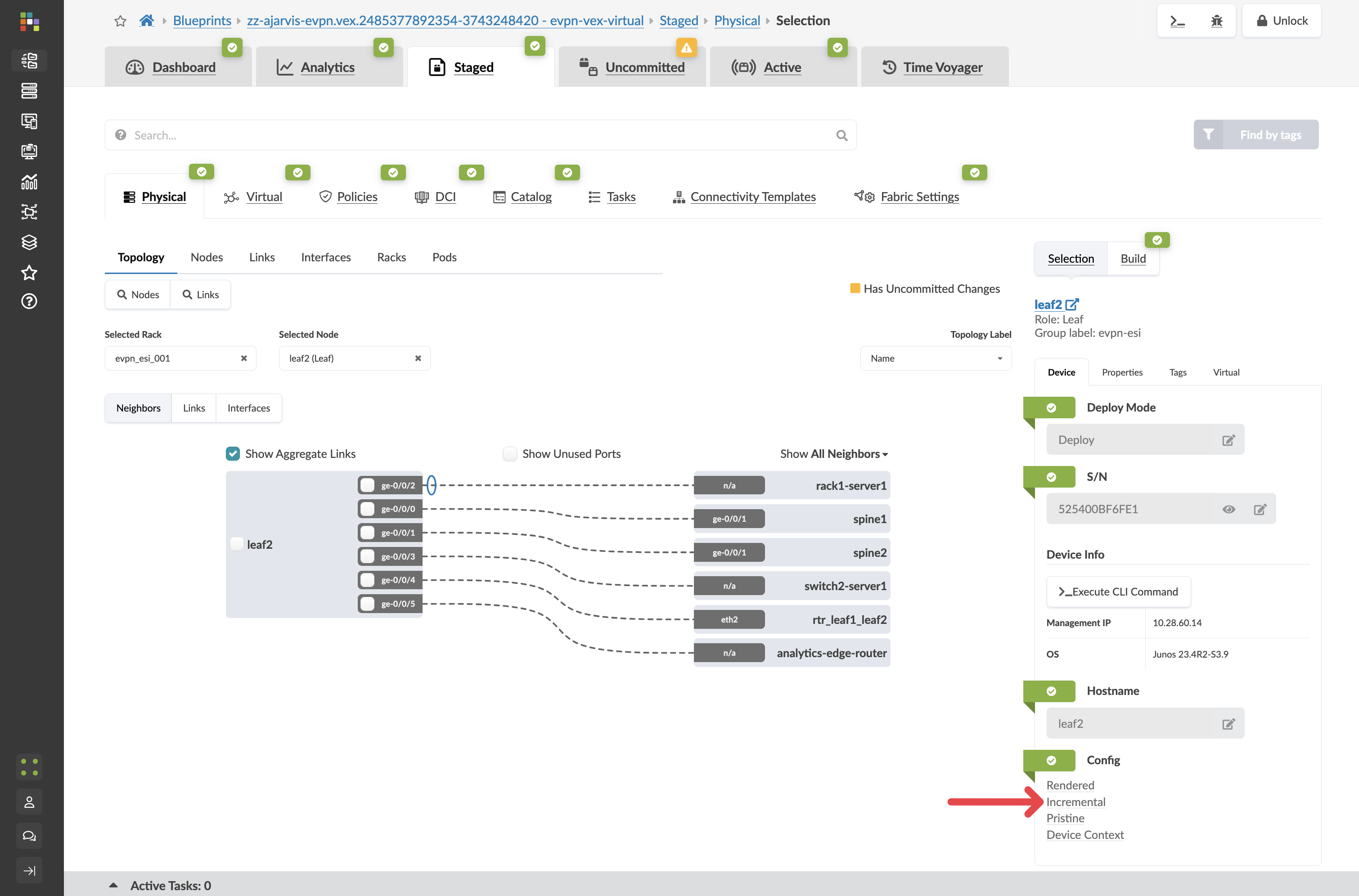
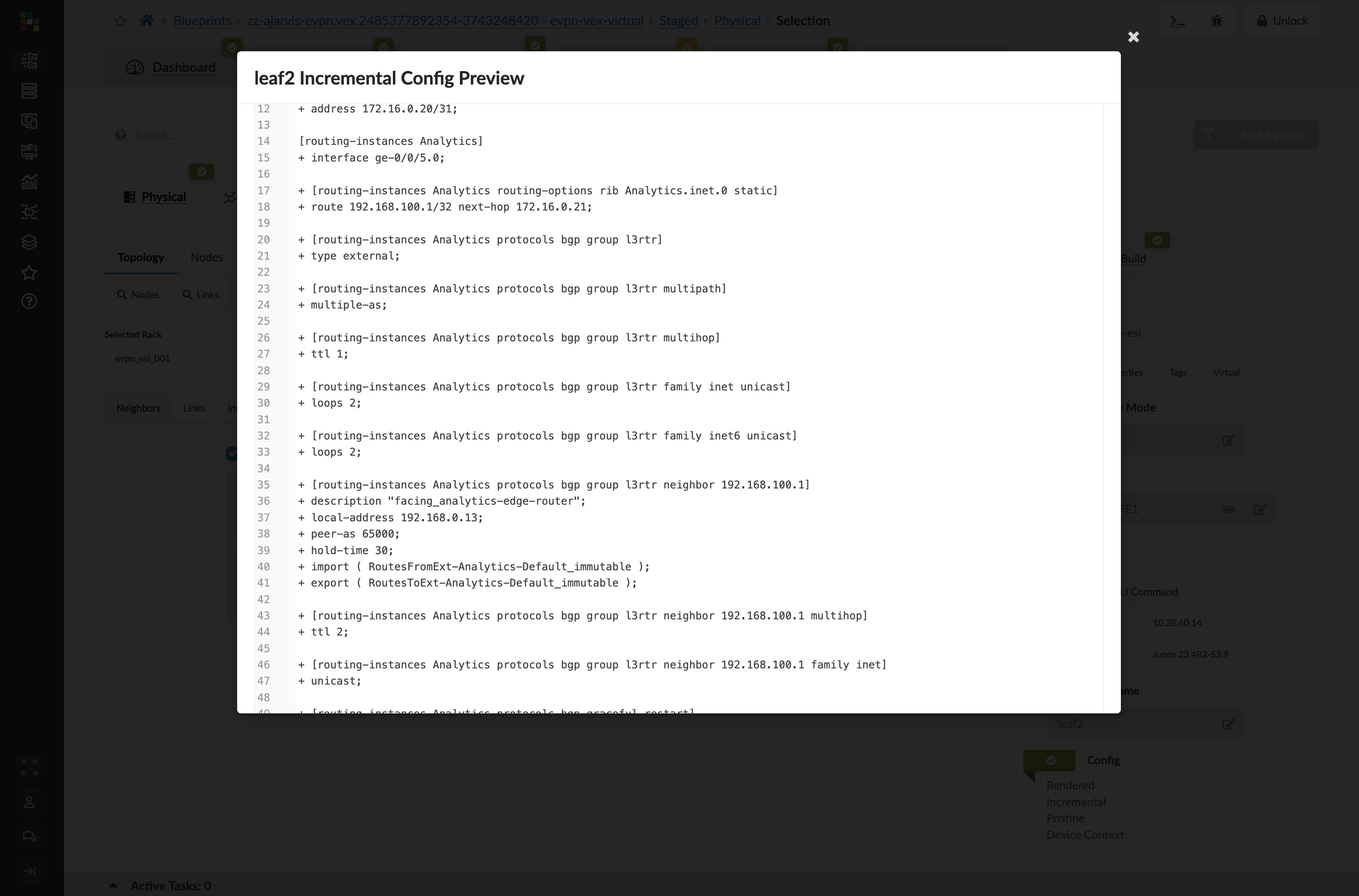
This will show you all of the incremental configuration that has been generated.
-
Click the Uncommitted tab to review your staged changes
-
Enter a commit message like "Added external connectivity for Analytics service" and click Commit
What You’ve Accomplished
You’ve just:
-
Created an external router connection for your Analytics service in "Undeploy" mode (meaning it’s modelled but not yet fully configured)
-
Set up BGP peering between your fabric and the external world
-
Connected your Layer 2 analytics-web network to this external router, which will serve as its gateway
-
Used a predefined connectivity template to simplify the configuration process
-
Had the option to customise routing policies for this specific connection
This external connectivity setup accomplishes two critical goals:
-
It provides a path for external users to access your Analytics service
-
It implements your security design by routing web tier traffic through an external firewall
In a traditional environment, setting up external connectivity is one of the most complex and risky operations. With Apstra, you’ve defined your intent for external connectivity, and the system has handled all the implementation details.
The Complete Analytics Service
Congratulations! You’ve now completed the entire deployment of your new Big Data Analytics service:
-
Expanded physical capacity by adding a new rack
-
Created network segmentation with a dedicated routing zone
-
Set up virtual networks for the web and database tiers
-
Connected servers to these networks
-
Established external connectivity for customer access
All of this was accomplished through Apstra’s intent-based approach, where you defined what you wanted to achieve, and the system handled the complex implementation details across your entire fabric.