Lab Guide 1 - Juniper
Day 2 Operations: Creating Virtual Networks
Scenario: Building Network Tiers for the Big Data Analytics Service
With our physical capacity expanded and a dedicated routing zone created, we now need to establish the network segments for our Big Data Analytics service. This service requires two separate network tiers:
-
A web-facing tier for the analytics dashboard and user interface, which requires extra security controls
-
A backend tier for the database and processing components
In Apstra, we’ll implement these as virtual networks within our Analytics routing zone.
Task: Create Virtual Networks for the Analytics Service
|
Reflection Point: In traditional networking, creating virtual networks would involve:
This process becomes exponentially complex as your network grows. |
Let’s see how Apstra simplifies this!
Step 1: Create the Analytics Web Tier Network (Layer 2 Only)
-
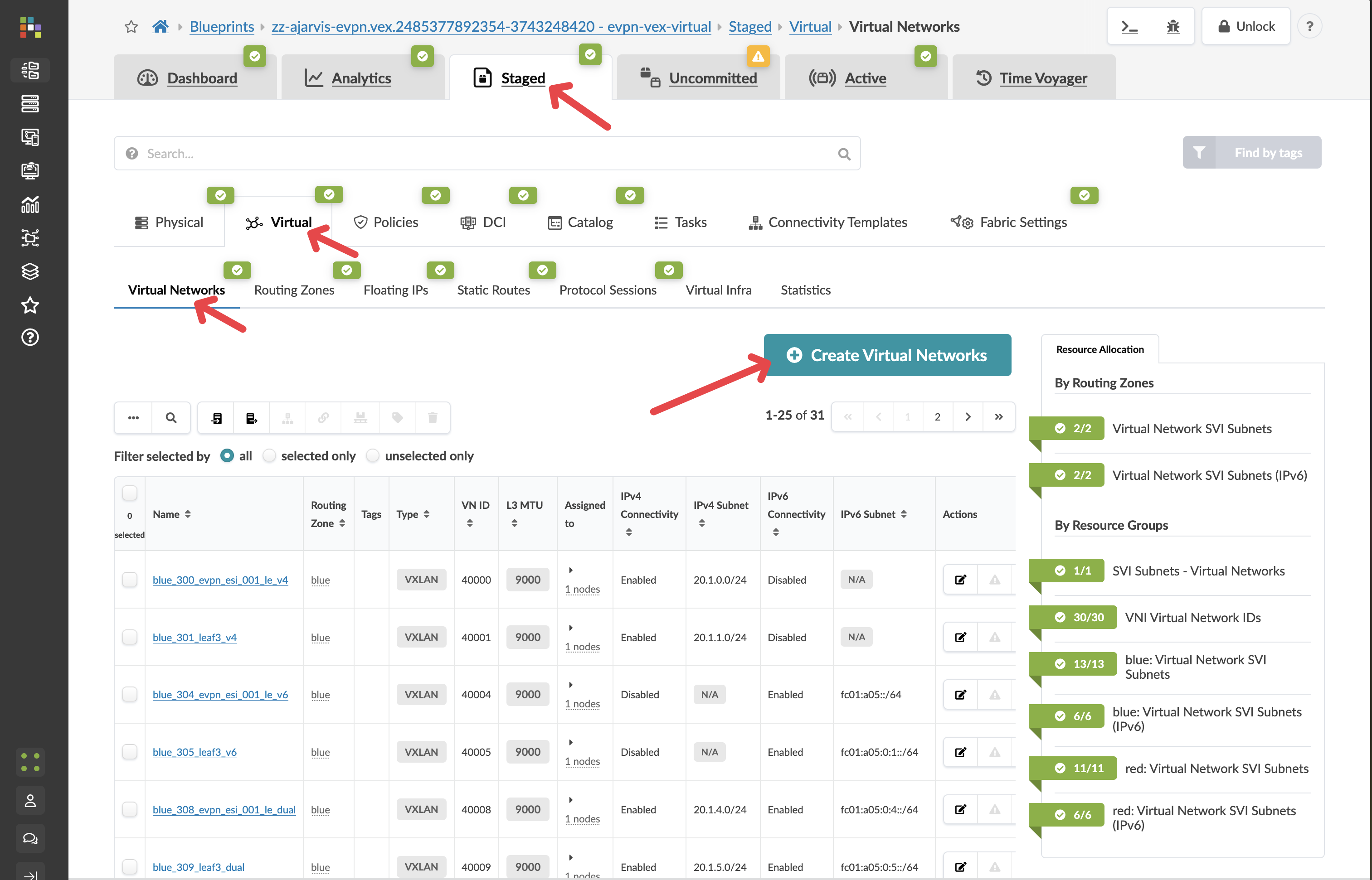
From the SE Demo blueprint, navigate to
-
Click Create Virtual Network
-
Configure the network with these settings:
Parameter Value Type
VXLAN
Name
analytics-web
Routing Zone
Analytics (the zone we just created)
IPv4 Connectivity
Disabled
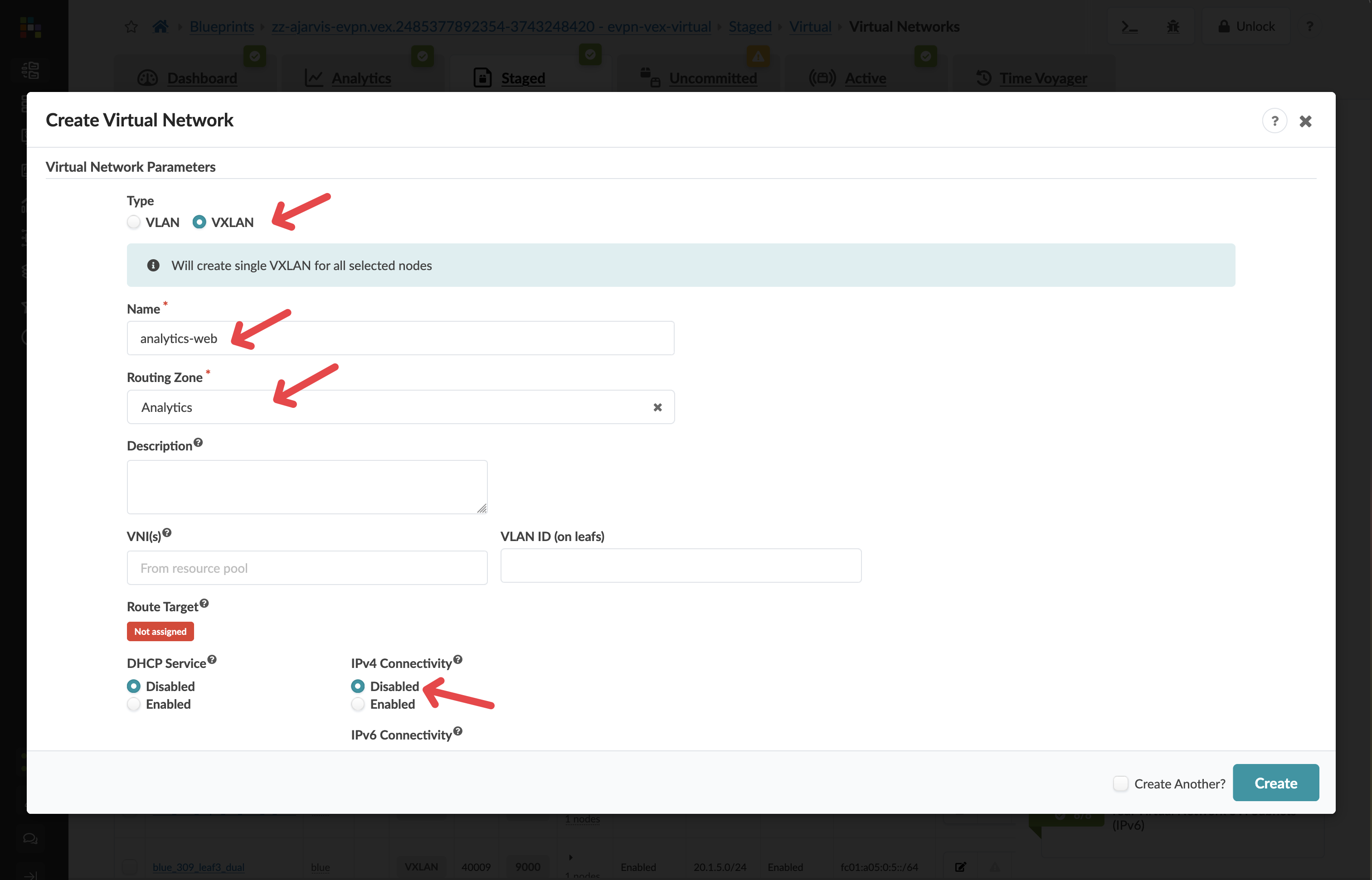
Security Design Decision: By disabling IPv4 Connectivity, we’re creating a Layer 2 only network (bridged overlay). This means:
-
The gateway for this network will reside on an external firewall, not on the leaf switches
-
This provides enhanced security for our customer-facing web tier, allowing for additional inspection and filtering of traffic
-
All inter-VLAN routing will pass through the firewall where security policies can be enforced
-
-
In the Create Connectivity Templates for section, select Tagged
-
In the Assigned To section, select all racks in your fabric
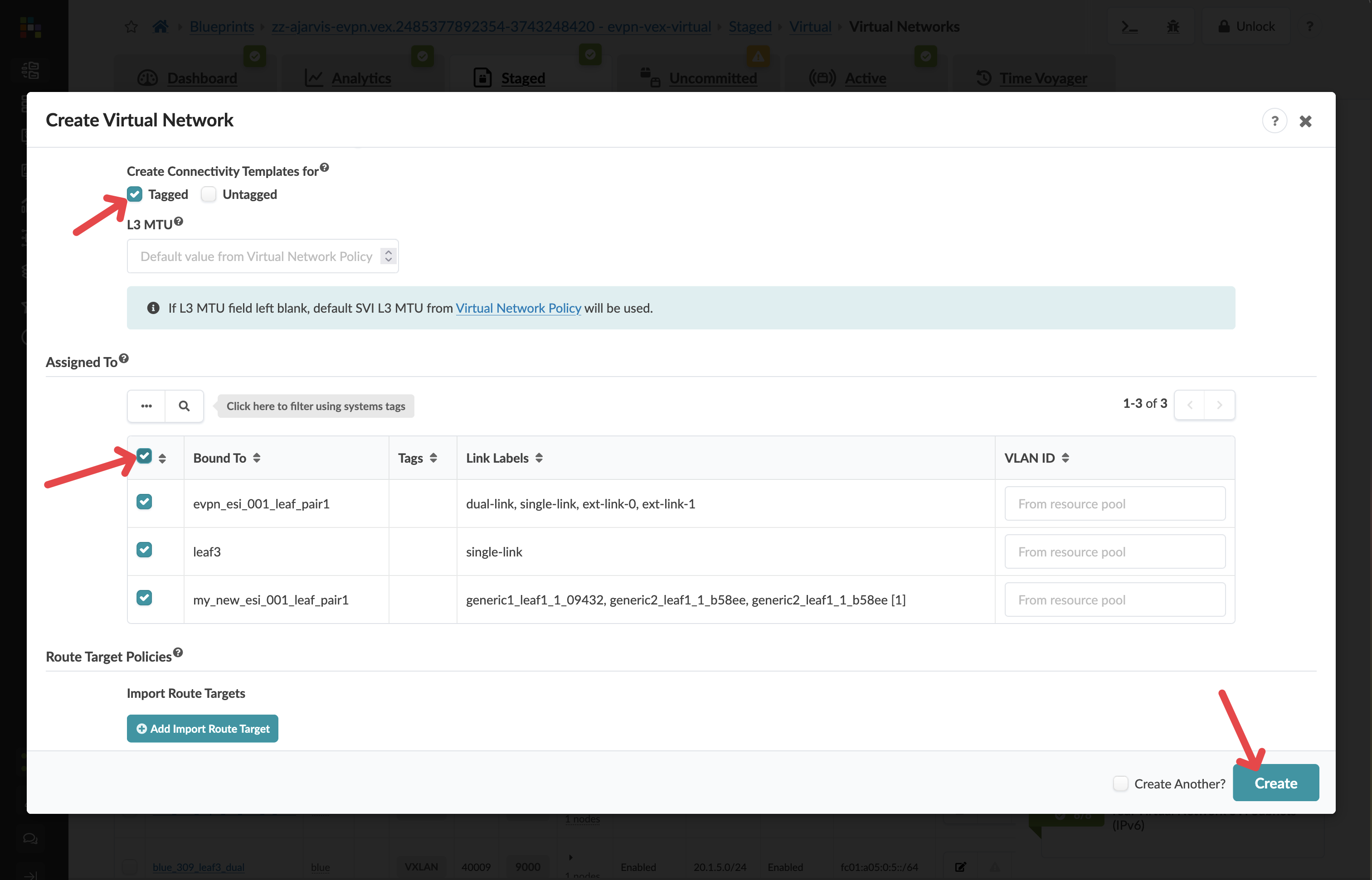
While you have the flexibility to deploy virtual networks selectively, in this case we want the web tier available across the entire fabric to allow for flexible workload placement.
-
Click Create to create the virtual network
Step 2: Create the Analytics Database Tier Network (Layer 3)
-
Click Create Virtual Network again
-
Configure the network with these settings:
Parameter Value Type
VXLAN
Name
analytics-db
Routing Zone
Analytics
IPv4 Connectivity
Enabled
IPv4 Subnet
10.1.2.0/24
Virtual Gateway IP
10.1.2.1
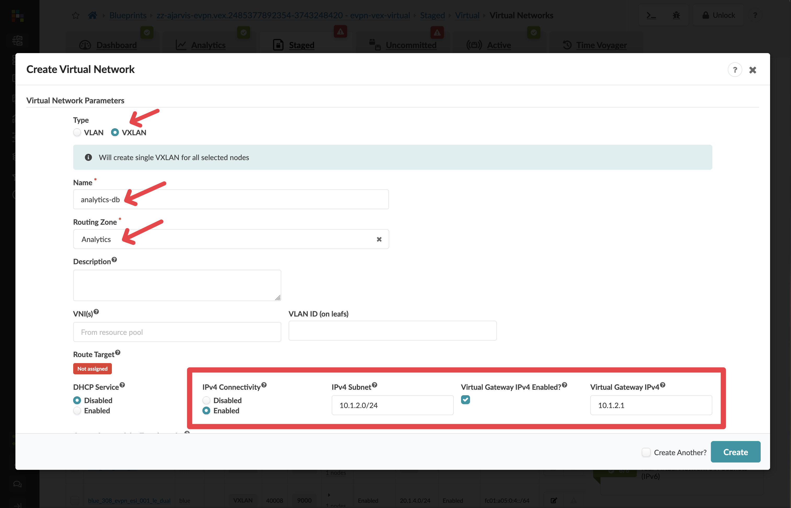
Network Design Note: For this network, we’ve enabled Layer 3 functionality:
-
This creates a gateway (10.1.2.1) directly on the leaf switches
-
Traffic can be routed between this network and others in the same routing zone
-
Instead of manually entering the subnet, you could have selected an IP pool, which would automatically assign the next available subnet from that pool
-
-
In the Create Connectivity Templates for section, select Tagged
-
In the Assigned To section, select all racks in your fabric
-
Click Create to create the second virtual network

Step 3: Assign Resources to Virtual Networks
There should not be any needed after creating the virtual networks, Apstra will identify any resources that need to be assigned:
-
If there are any red resource indicators, click them and assign the appropriate pools
-
Click Save to complete the assignments
Step 4: Assign Resources to the Routing Zone
After creating the virtual networks to switches, Apstra will identify any resources that need to be assigned under the routing zone:
|
Why? Previously we added the routing zone, but the configuration was never pushed because no virtual network using that routing zone existed. Now we’re actually pushing our virtual networks to every switch. The fabric requires loopbacks in order to operate. In this example, we actually have IPv4 and IPv6 turned on, hence why loopbacks for both address types are needed. |
-
If there are any red resource indicators, click them and assign any of the pools
-
Click Save to complete the assignments
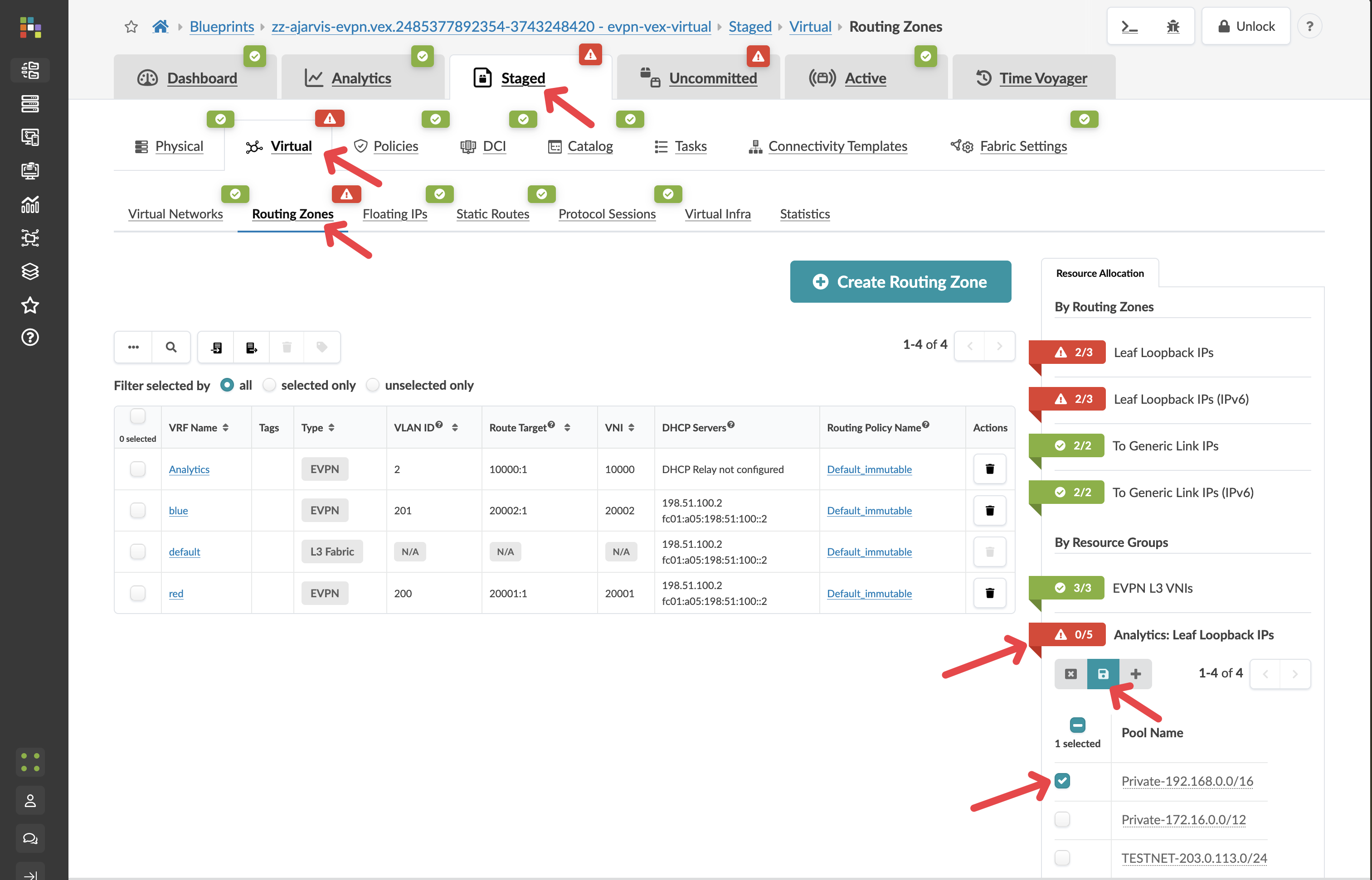
Apstra has now autoassigned all of the needed loopback addresses.
Step 5: Review and Commit Your Changes
Before you commit on your blueprint, let’s examine how Apstra has automated the complete configuration of your devices:
-
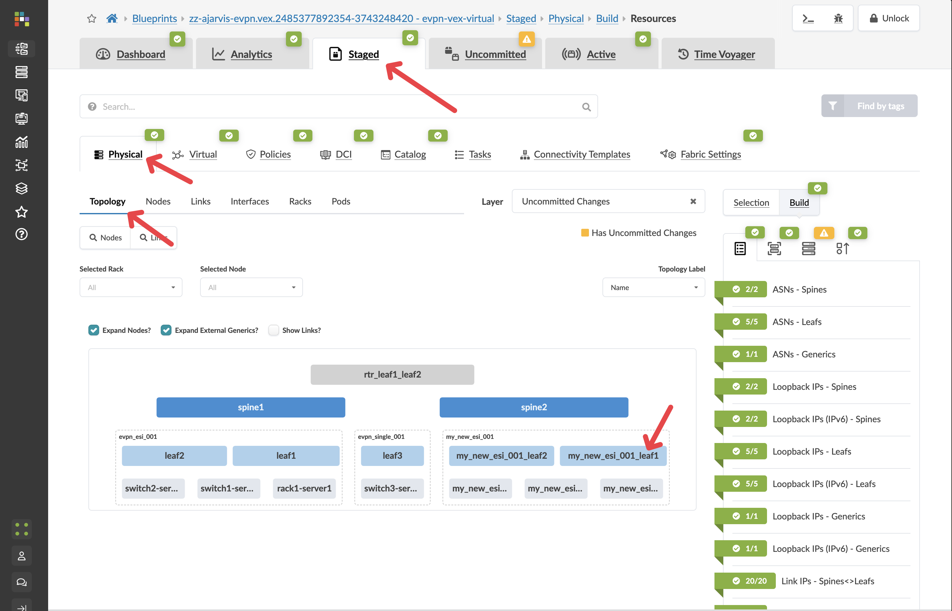
Navigate to Staged > Physical > Devices
-
Select one of your leaf switches by clicking on it
-
Click on the Incrimental Configuration tab
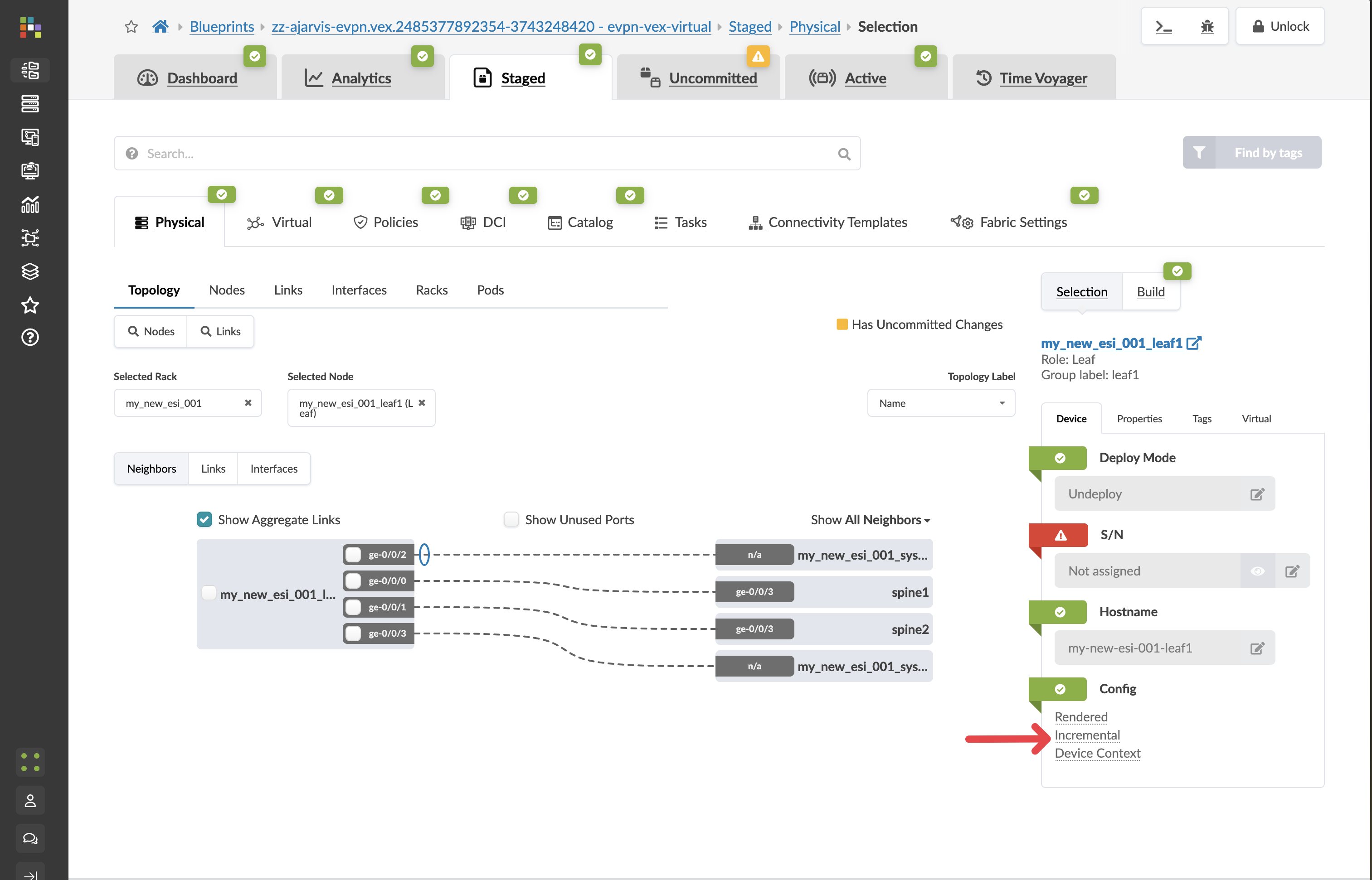
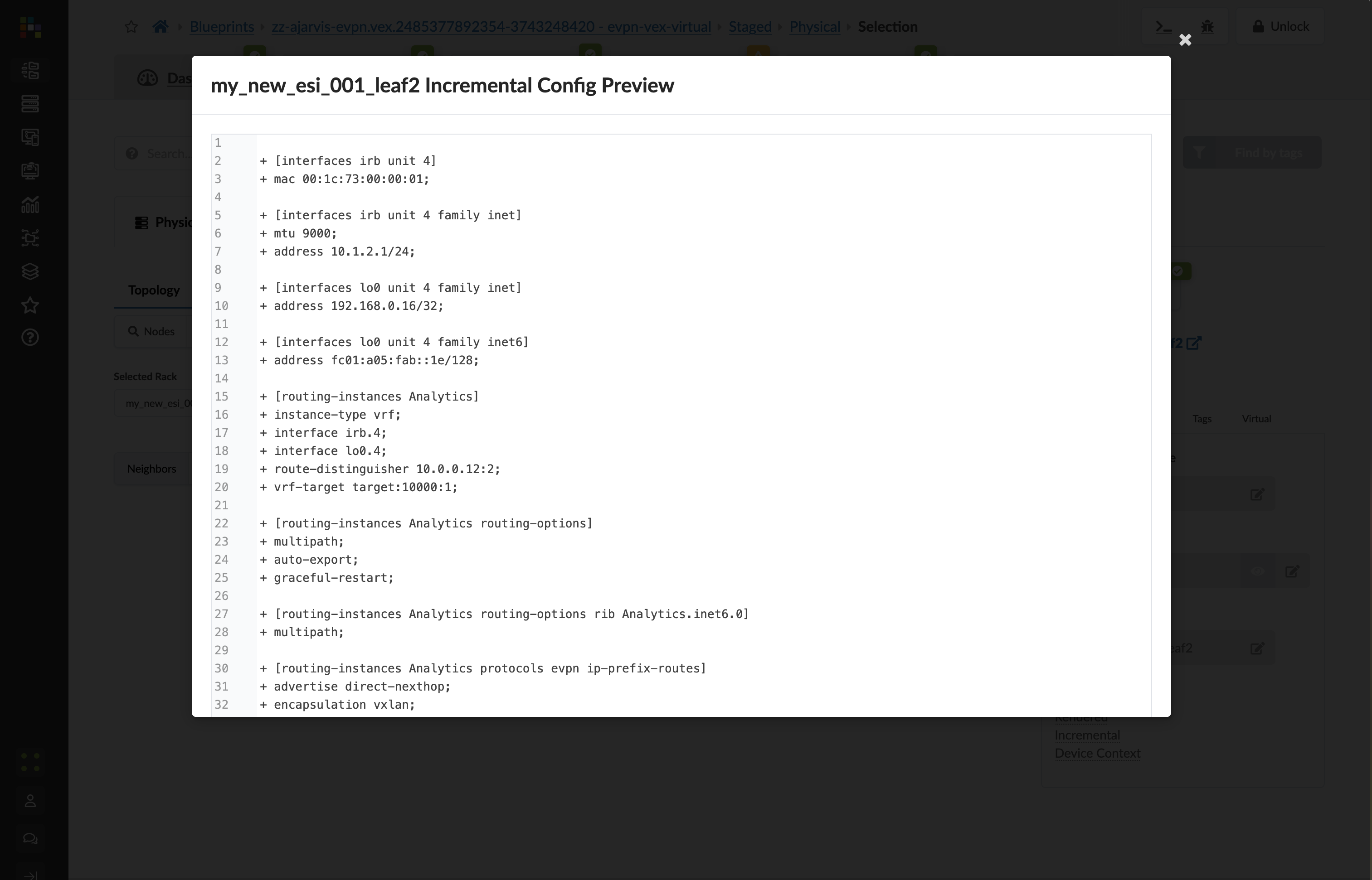
This will show you all of the incremental configuration that has been generated based on the very few clicks you’ve had to do. You have successfully now deployed a new VRF and multiple VXLAN overlays, not to mention the adjustments that are needed to the EVPN protocol configuration.
-
Click the Uncommitted tab to see your staged changes
Review the changes Apstra is preparing to make across your fabric
-
Enter a commit message like "Added Analytics virtual networks" and click Commit
What You’ve Accomplished
You’ve just:
-
Created a Layer 2 only network for your web tier, where gateways will be hosted on an external firewall for enhanced security
-
Created a Layer 3 virtual network for your database tier, with integrated routing on the leaf switches
-
Deployed both networks across all racks for maximum flexibility
-
Let Apstra handle all the complex VXLAN, VRF, and routing configurations automatically
In a traditional environment, creating these network segments would require configuring VLANs, VXLANs, SVIs, routing policies, and more across multiple devices. With Apstra, you simply declare what networks you need and their characteristics, and the system handles all implementation details consistently across your fabric.
Next, we’ll connect servers to these new virtual networks to complete our Analytics service deployment.