Lab Guide 1 - Juniper
Day 2 Operations: Applying Connectivity Templates
Scenario: Connecting Servers to the Analytics Networks
Now that we’ve added our analytics server to the fabric, we need to connect it to the virtual networks we created. In traditional networking, this would involve configuring VLANs on the switch ports connected to the server, possibly with trunk configurations and careful tracking of which VLANs are allowed.
Apstra simplifies this process using Connectivity Templates, which define how servers connect to virtual networks. By applying these templates to server interfaces, Apstra automatically configures the appropriate switch ports.
Task: Apply Connectivity Templates to Analytics Server
Step 1: Understand Connectivity Templates
Connectivity Templates define how endpoints connect to your network. They can be:
-
Auto-generated when you create a virtual network
-
Custom-created for specific connectivity scenarios
When we created our virtual networks earlier, Apstra automatically generated connectivity templates for each one. Now we’ll use these to connect our server.
|
If you don’t have these let us know but you need to go back to the virtual network tab, select the virtual networks and you’ll see an export symbol. |
Step 2: Locate the Connectivity Templates
-
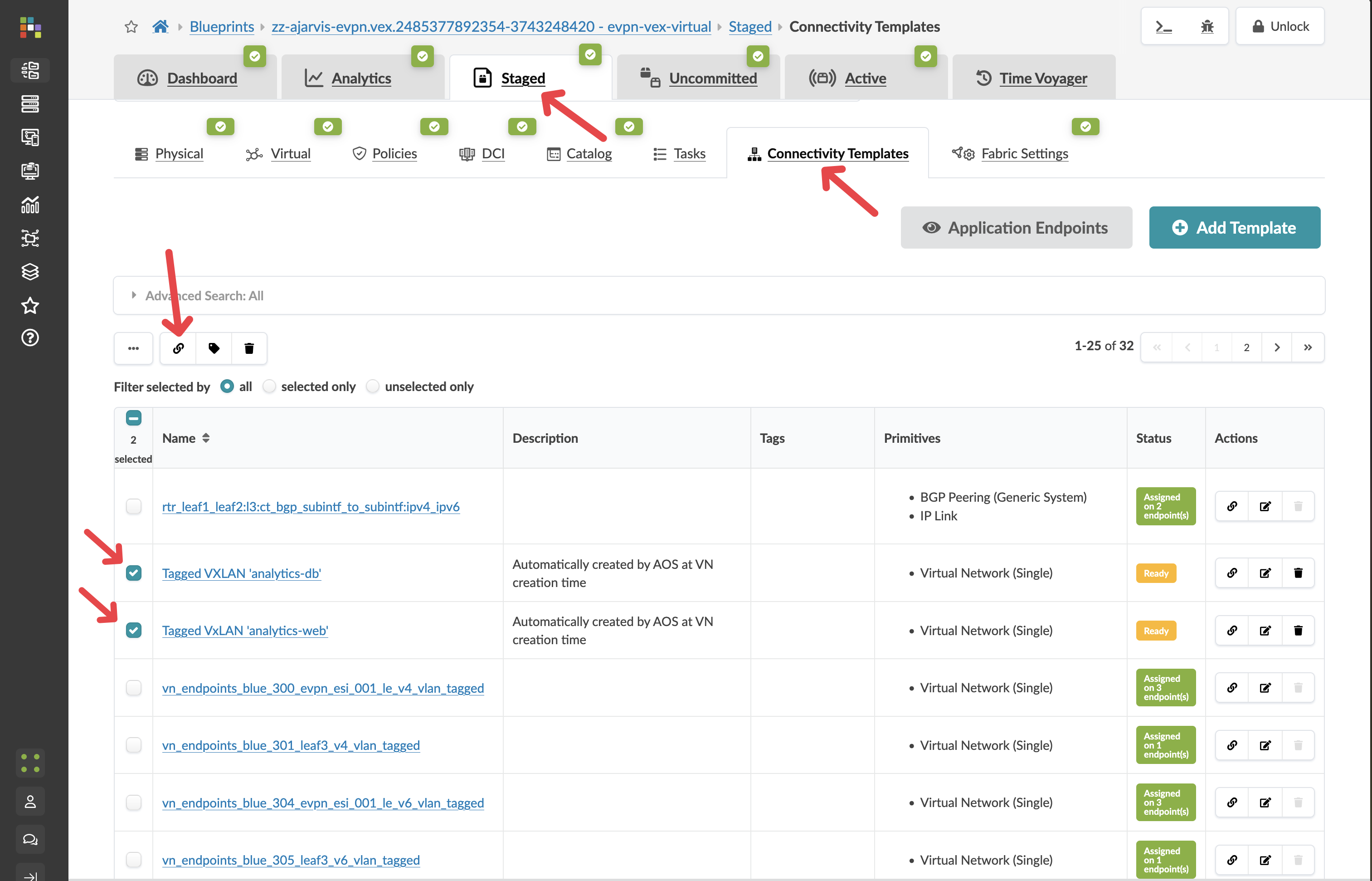
From the SE Demo blueprint, navigate to
-
You should see templates for the virtual networks we created:
-
Tagged VxLAN 'analytics-web' - This template connects endpoints to our web tier
-
Tagged VxLAN 'analytics-db' - This template connects endpoints to our database tier
-
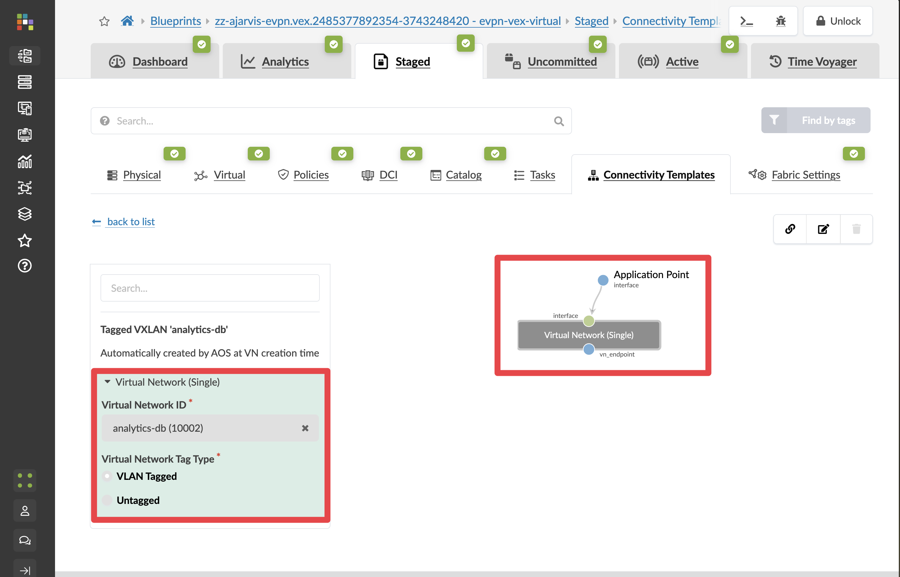
By clicking on one of the connectivity templates, you can see how they are built and we will explore this in the next section.
Step 3: Assign the Analytics-Web & Analytics-DB Template to Server Interfaces
-
Return to the Connectivity Templates view
-
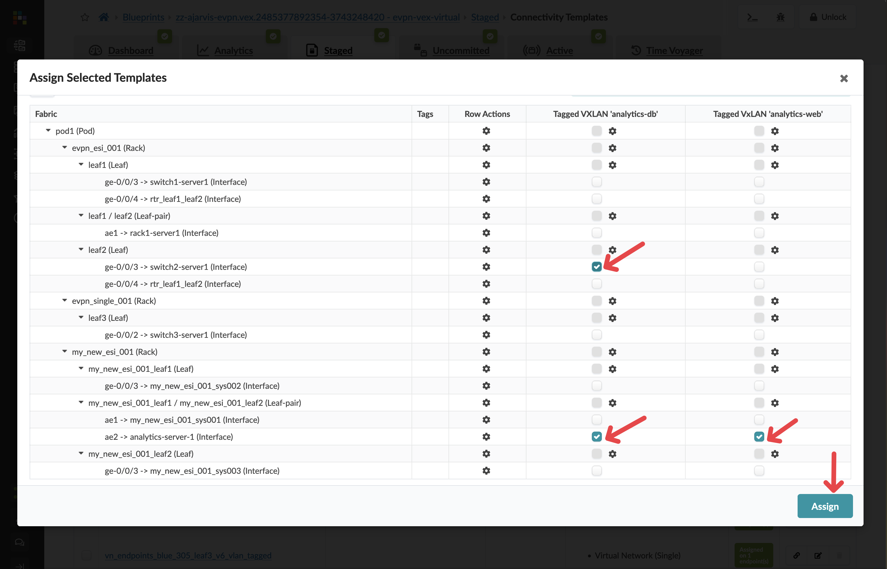
Select both Tagged VxLAN 'analytics-web' and Tagged VxLAN 'analytics-db' templates and click the Assign icon at the top

-
Check the boxes next to the same interfaces for your analytics server
-
Click the Assign button
|
What’s happening: Apstra is now configuring these ports facing the analytics server. Since this is a Layer 2 network, the switch ports will be configured to carry the VLANs that are automatically mapped to the VXLANs, and the server will now be able send and receive traffic from these networks. |
|
Multi-VLAN Access: By assigning both templates to the same interfaces, the port can carry both VLANs. The server can now access both networks, which is perfect for an analytics application that needs both web and database tiers. |
Step 4: Understand What Apstra Is Automating
When you assign connectivity templates, Apstra is automatically:
-
Configuring VLANs on the switch ports
-
Setting up trunk ports with the appropriate allowed VLANs
-
Mapping VLANs to VXLANs for fabric-wide transport
-
Creating Redundancy Groups when needed such as EVPN ESI LAGs
-
Ensuring consistency across redundant connections
-
Documenting connectivity in the single source of truth
This eliminates manual port configuration and significantly reduces the chance of errors.
Step 5: Review and Commit Your Changes
Before you commit on your blueprint, let’s examine how Apstra has automated the complete configuration of your devices:
-
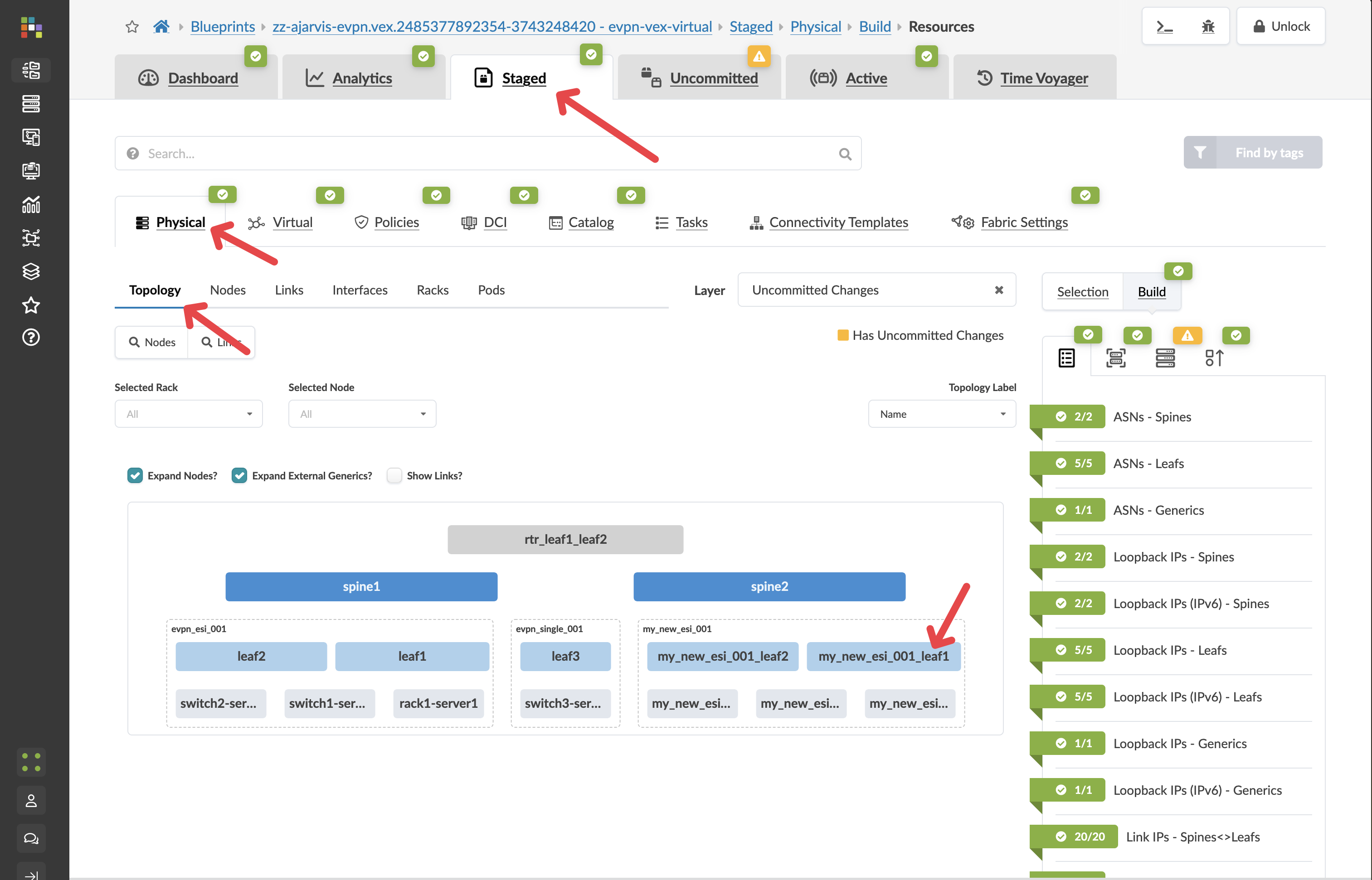
Navigate to Staged > Physical > Devices
-
Select one of your leaf switches by clicking on it
-
Click on the Incrimental Configuration tab
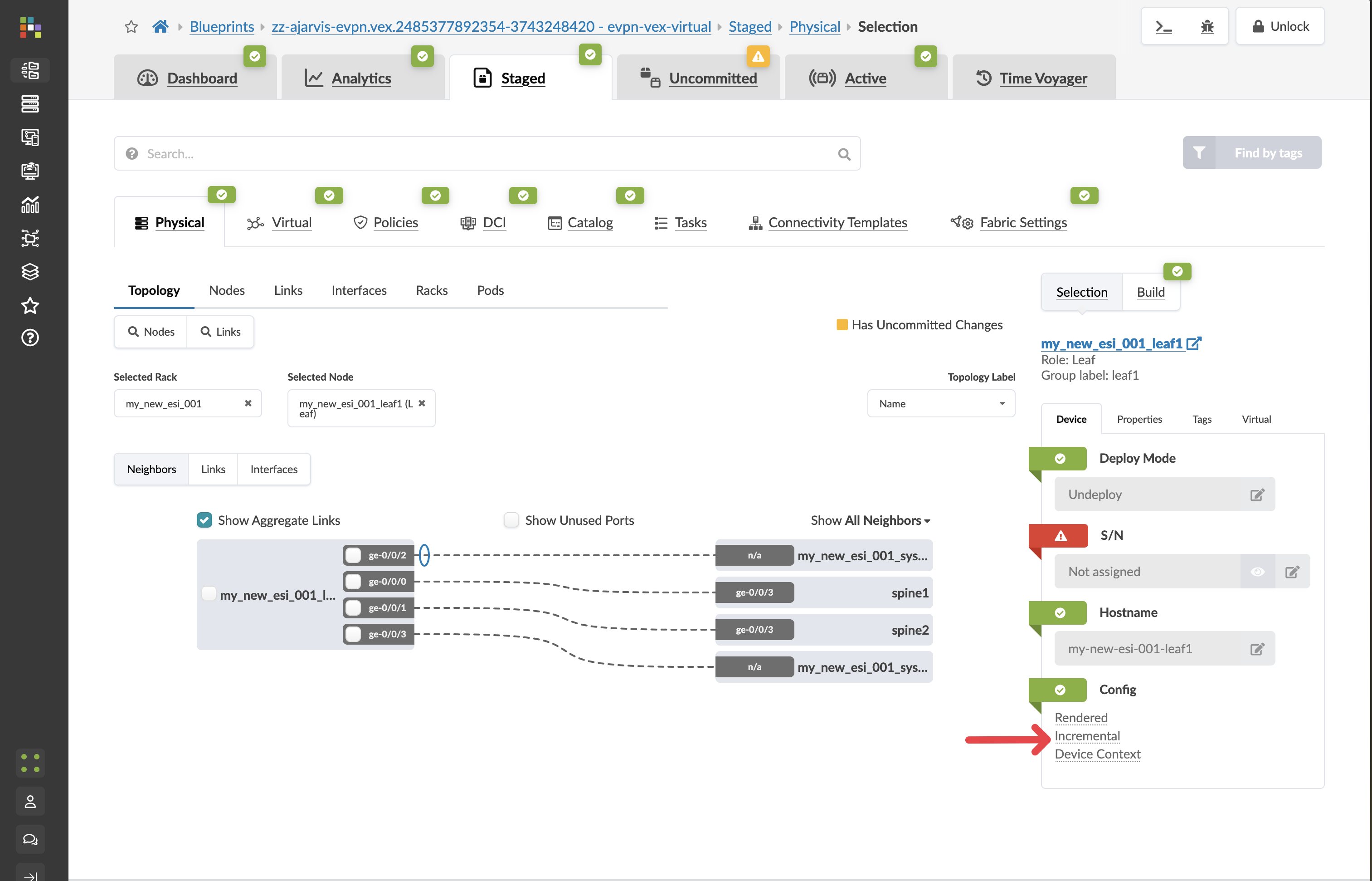
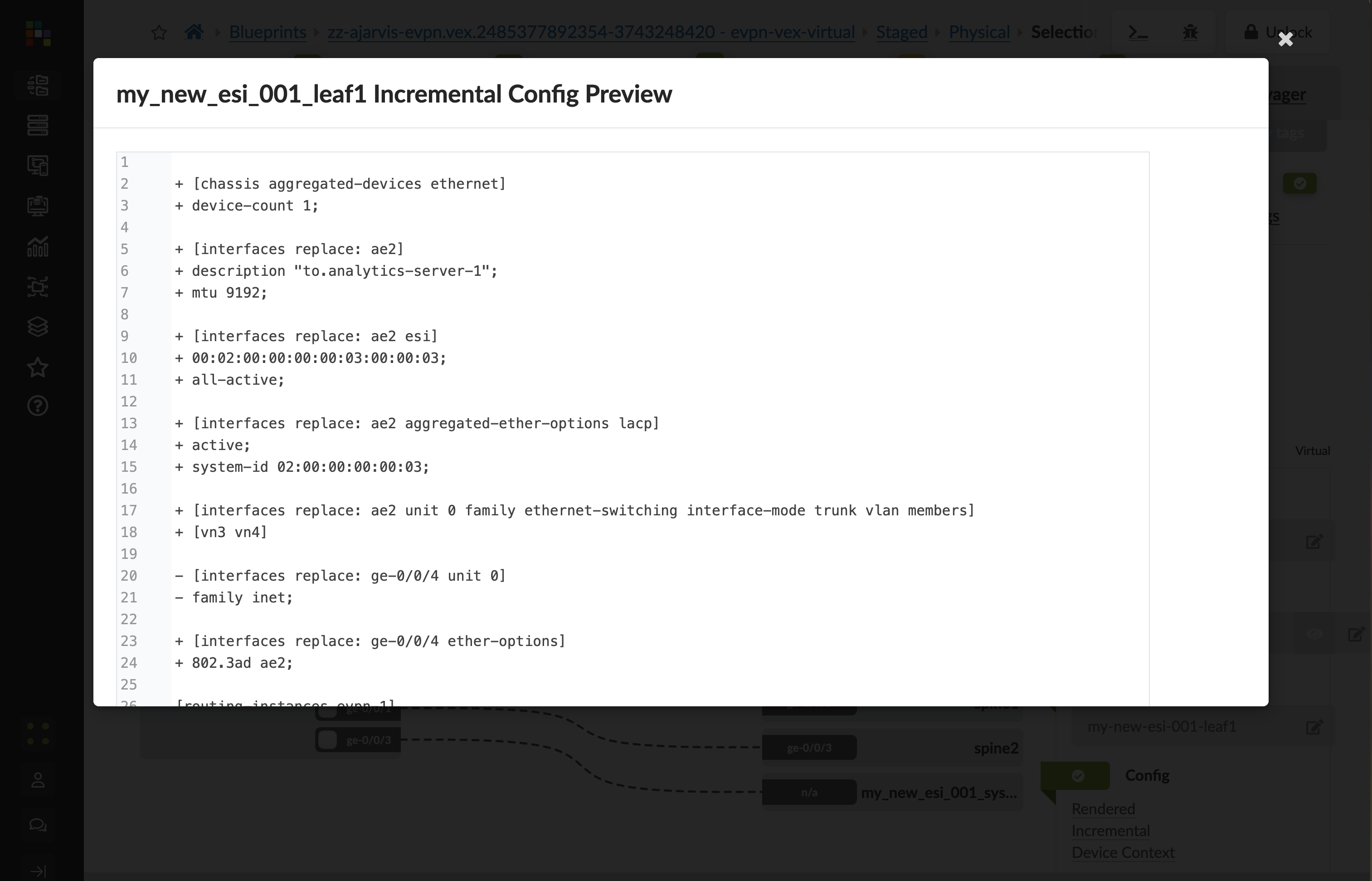
This will show you all of the incremental configuration that has been generated.
-
Click the Uncommitted tab to see your staged changes
-
Review the port configurations Apstra will apply
-
Enter a commit message like "Connected analytics server to virtual networks" and click Commit
What You’ve Accomplished
You’ve just:
-
Connected your analytics server to both the web and database networks
-
Automated the VLAN and port configurations on the leaf switches
-
Documented this connectivity in your network’s single source of truth
Your server is now connected to both virtual networks and can communicate with other devices in these networks. This completes the internal configuration of our Analytics platform.
Next, we’ll set up external connectivity to allow outside access to our Analytics service.