Lab Guide 1 - Juniper
Understanding Apstra’s Building Blocks
How Apstra Models Network Hardware
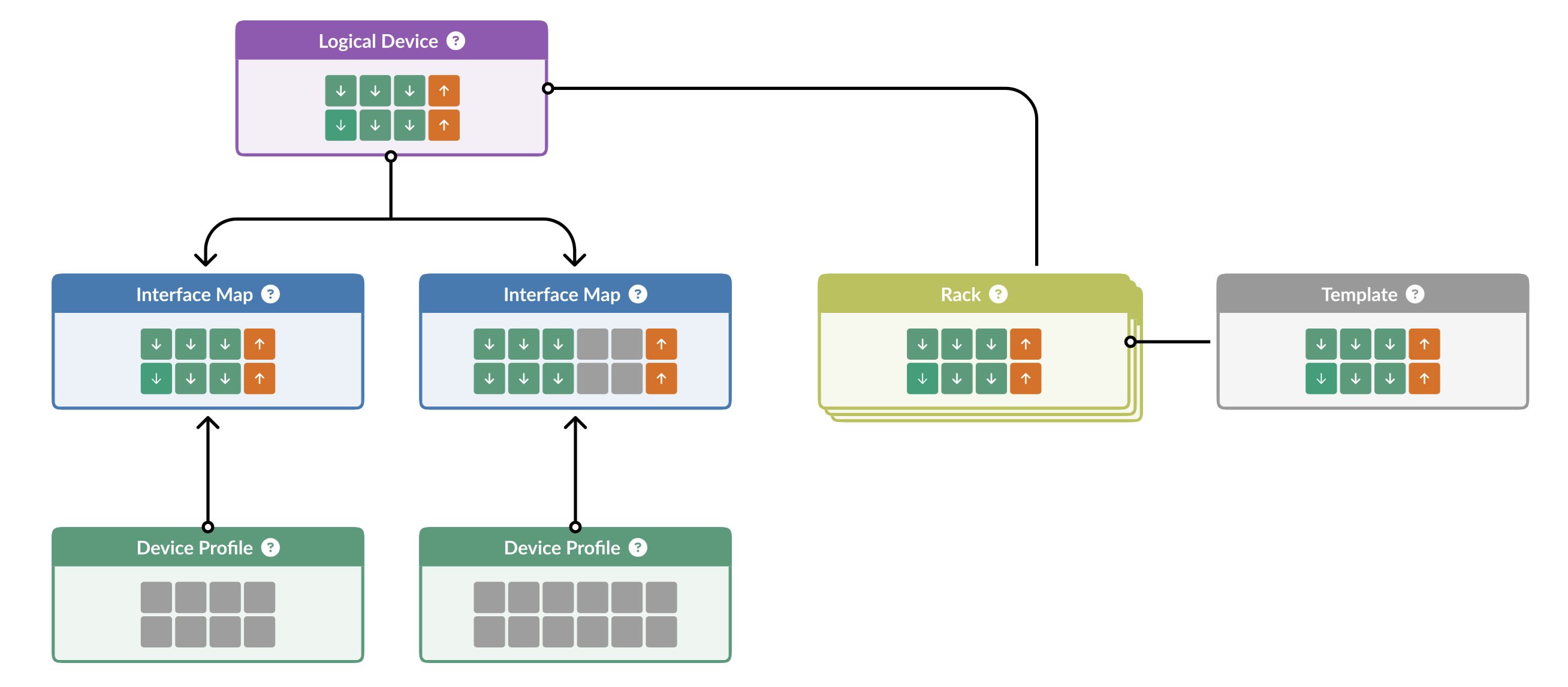
The diagram below illustrates the three key components Apstra uses to model network devices:

Let’s explore each of these components and how they work together to create Apstra’s powerful abstraction layer:
Logical Devices
What they are: Complete abstractions that define the capabilities of a network device, independent of any physical hardware. They specify:
-
Number of ports
-
Port speeds
-
Breakout capabilities
Key insight: A single Logical Device can represent switches from multiple vendors. For example, a "48x10G + 6x100G" Logical Device could represent similar switches from Juniper, Cisco, Arista, or any other vendor. Most vendors offer switches with nearly identical port configurations, making this abstraction extremely powerful.
Think of Logical Devices as the functional blueprint of what a switch can do, completely separated from the details of who manufactured it or how it’s physically constructed.
Device Profiles
What they are: Pre-defined, thoroughly tested representations of specific hardware platforms that are shipped with Apstra.
What they contain:
-
Technical specifications for each supported physical or virtual device
-
Vendor-specific details needed to configure and monitor the device
-
Software compatibility information
Device Profiles are created and maintained by Apstra engineering, ensuring that each supported platform works seamlessly with the system. They contain all the vendor-specific knowledge that Apstra needs to properly manage each physical device.
Think of Device Profiles as the vendor-specific knowledge base that allows Apstra to properly manage different hardware platforms.
Interface Maps
What they are: The critical "glue" that connects abstract Logical Devices to physical hardware when you’re ready to deploy.
How they work:
-
Map the abstract ports defined in a Logical Device to the actual physical interfaces on a specific switch
-
Enable the transition from design (software) to deployment (hardware)
-
Activated when you add a device to a blueprint and commit configuration
Think of Interface Maps as the translation layer that connects your abstract design to the physical reality of your data centre.
Why This Abstraction Is Revolutionary
This abstraction layer is the foundational principle that enables Apstra’s most powerful capabilities:
-
Design Without Hardware: Model your entire data centre network in software without owning a single physical switch
-
True Multi-Vendor Support: Mix and match hardware from different vendors in the same blueprint
-
Vendor Independence: Change hardware vendors without changing your network design
-
Future-Proofing: Swap in new hardware generations while maintaining the same logical design
-
Focus on Intent: Design based on what you need your network to do, not vendor-specific implementation details
The beauty of this approach is that you can design your entire network based on capabilities and intent, then decide which specific hardware to deploy later. You can even change vendors for different parts of your network, or replace hardware with a different vendor’s equipment later, all while maintaining the same logical design.
For this Test Drive, these components have been pre-configured for you to save time. As you continue to explore Apstra, you’ll gain a deeper appreciation for how this abstraction layer simplifies network design, deployment, and management.
Now that we understand these foundational elements, let’s move on to creating Rack Types that will form the physical structure of our data centre design.