Lab Guide 1 - Juniper
Creating and Configuring a Blueprint
A Blueprint is a deployable instance of your template. While a template is the general design for your network, a blueprint is the specific implementation that will be deployed to your actual devices.
In this exercise, we’ll:
-
Create a blueprint from the template we just built
-
Assign all necessary network resources (ASNs and IP pools)
-
Save our work with our first blueprint commit
Exercise 1: Create a Blueprint
-
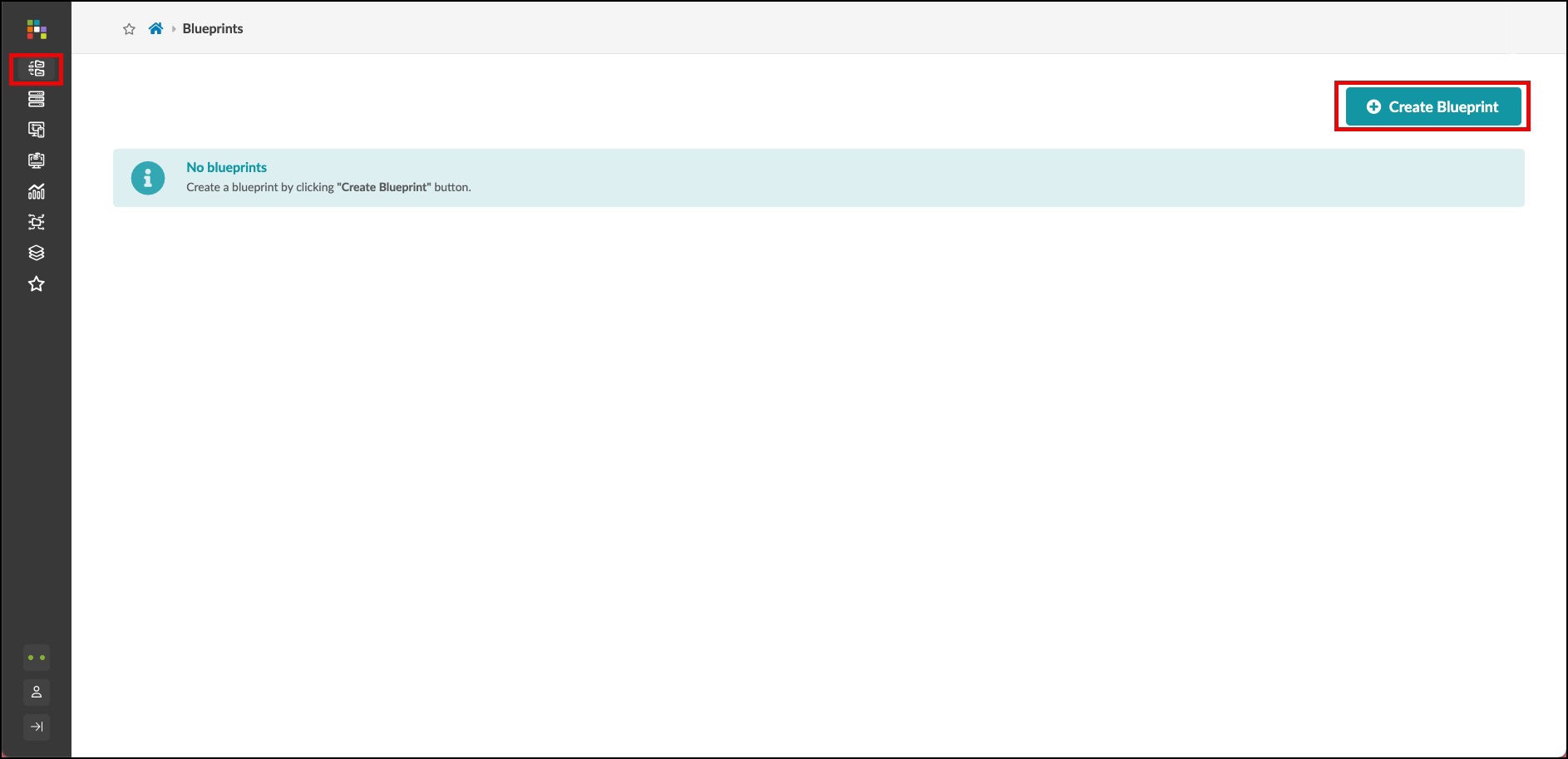
Click Blueprints, then click Create Blueprint
-
Configure your blueprint:
Field Value Name
your_name-pod1
Template
your_name_fabric
-
A preview of the blueprint’s intent will appear. Review it and click Create
-
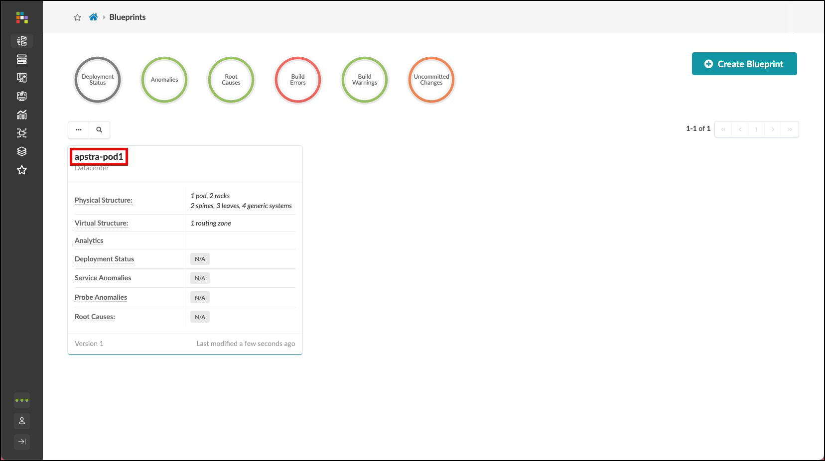
For a moment, you’ll see Apstra "scaffolding" the blueprint - creating all the necessary components from your template
-
Once complete, click the blueprint name to see its dashboard
Exercise 2: Assign Resources
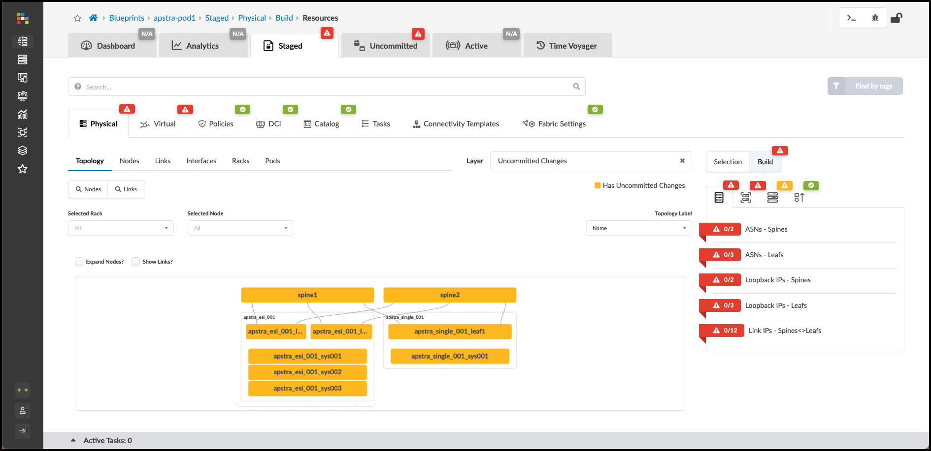
You’ll notice red indicators showing where resource assignments are needed. These are places where specific values (like IP addresses or ASNs) need to be assigned before the blueprint can be deployed. Let’s assign all the necessary resources to our blueprint.
| The specific pools we’re using in this exercise are pre-configured examples. In your production environment, you can use any non-overlapping address ranges. Apstra will always validate that no IP address or ASN overlaps exist in the fabric. |
Assign ASN Resources
-
From the blueprint, navigate to
-
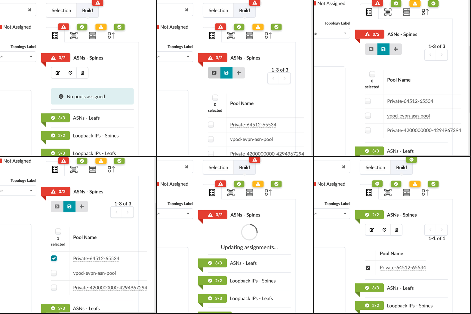
Click the red status indicator next to ASNs - Spines, then click Update assignments
-
Select the Private-64512-65534 pool from the dropdown
-
Click Save. The red status indicator should turn green, indicating a successful assignment.
-
Repeat the same process for ASNs - Leafs, also selecting the Private-64512-65534 pool.
Assign IP Address Resources
Now let’s assign IP addressing for device loopbacks and fabric links:
-
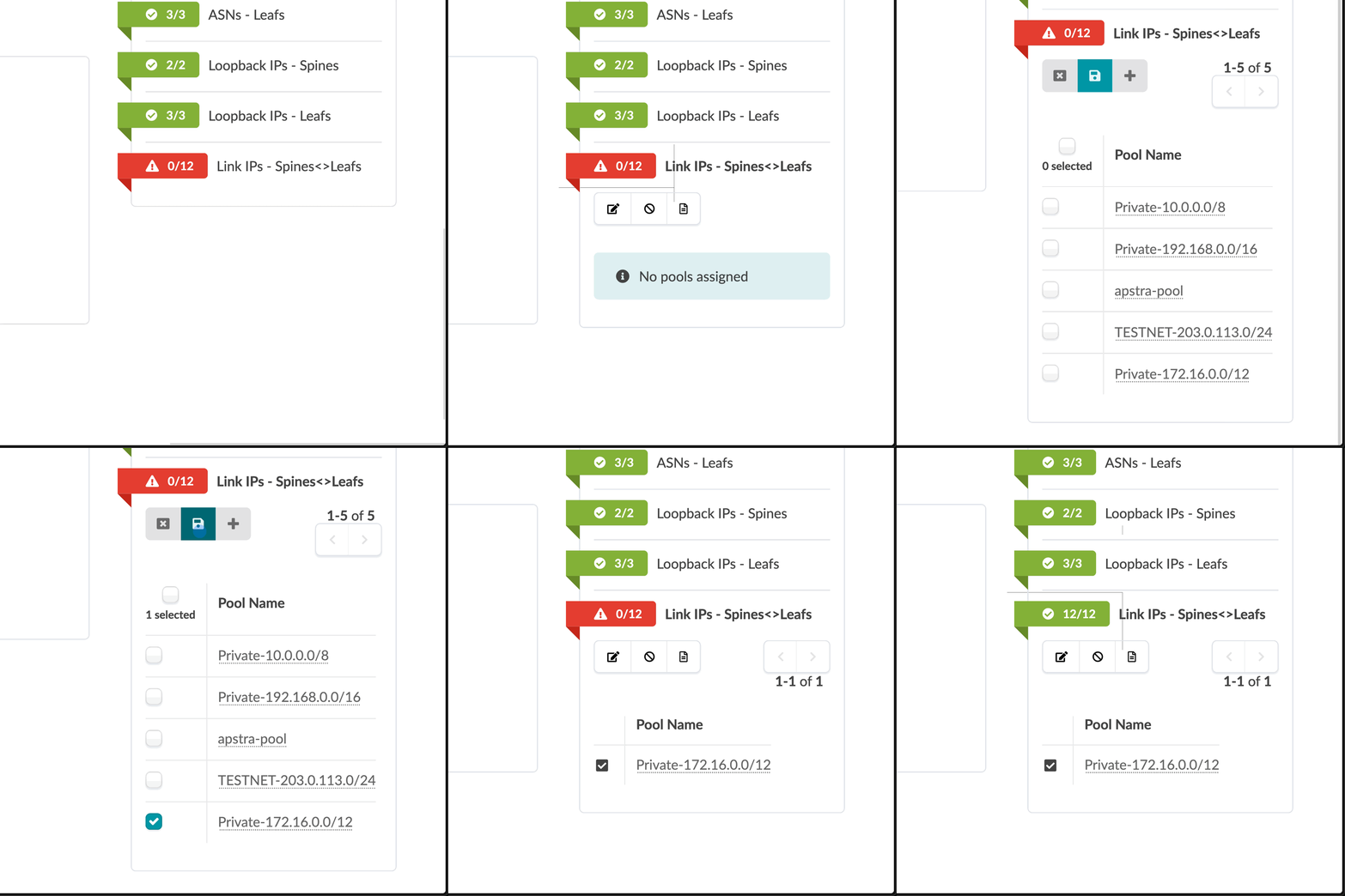
While still in the Resources tab, click the red status indicator next to Loopback IPs - Spines
-
Click Update assignments and select the Private-192.168.0.0/16 pool
-
Click Save to apply the assignment
-
Repeat for Loopback IPs - Leafs, also selecting the Private-192.168.0.0/16 pool
-
Next, click the red status indicator next to Link IPs - Spines<>Leafs
-
Click Update assignments and select the Private-172.16.0.0/12 pool
-
Click Save to apply the assignment
-
Verify that all resource indicators have turned green, indicating successful assignments
|
Pro Tip: Apstra automatically manages the allocation of addresses from these pools, ensuring there are no conflicts or overlaps. The system keeps track of all allocations and maintains the single source of truth for your network. |
Assign Interface Maps and Perform Our First Commit
This is where we’re now telling Apstra what the underlying device will be, and this will enable it to take all of that intent and generate configuration for the switches you’ll actually be using.
-
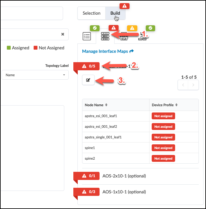
To the right of the Resources tab, select the Device Profiles tab.
-
Click the red status indicator next to virtual-7x10⁻¹, then click the Change interface maps assignment button.
-
Select interface maps for each device as shown in the table below.
Table 1. Table Interface Map Assignment Values Name Interface Map evpn_esi_001_leaf1
Juniper_vEX__slicer-7x10⁻¹
evpn_esi_001_leaf2
Juniper_vEX__slicer-7x10⁻¹
evpn_single_001_leaf1
Juniper_vEX__slicer-7x10⁻¹
spine1
Juniper_vEX__slicer-7x10⁻¹
spine2
Juniper_vEX__slicer-7x10⁻¹
-
Click Update Assignments to assign the device models and return to the build page. After a moment the red status indicator turns green indicating that the assignment was successful.
Exercise 3: Review the Rendered Configuration
Before you do your first commit on your blueprint, let’s examine how Apstra has automated the complete configuration of your devices:
-
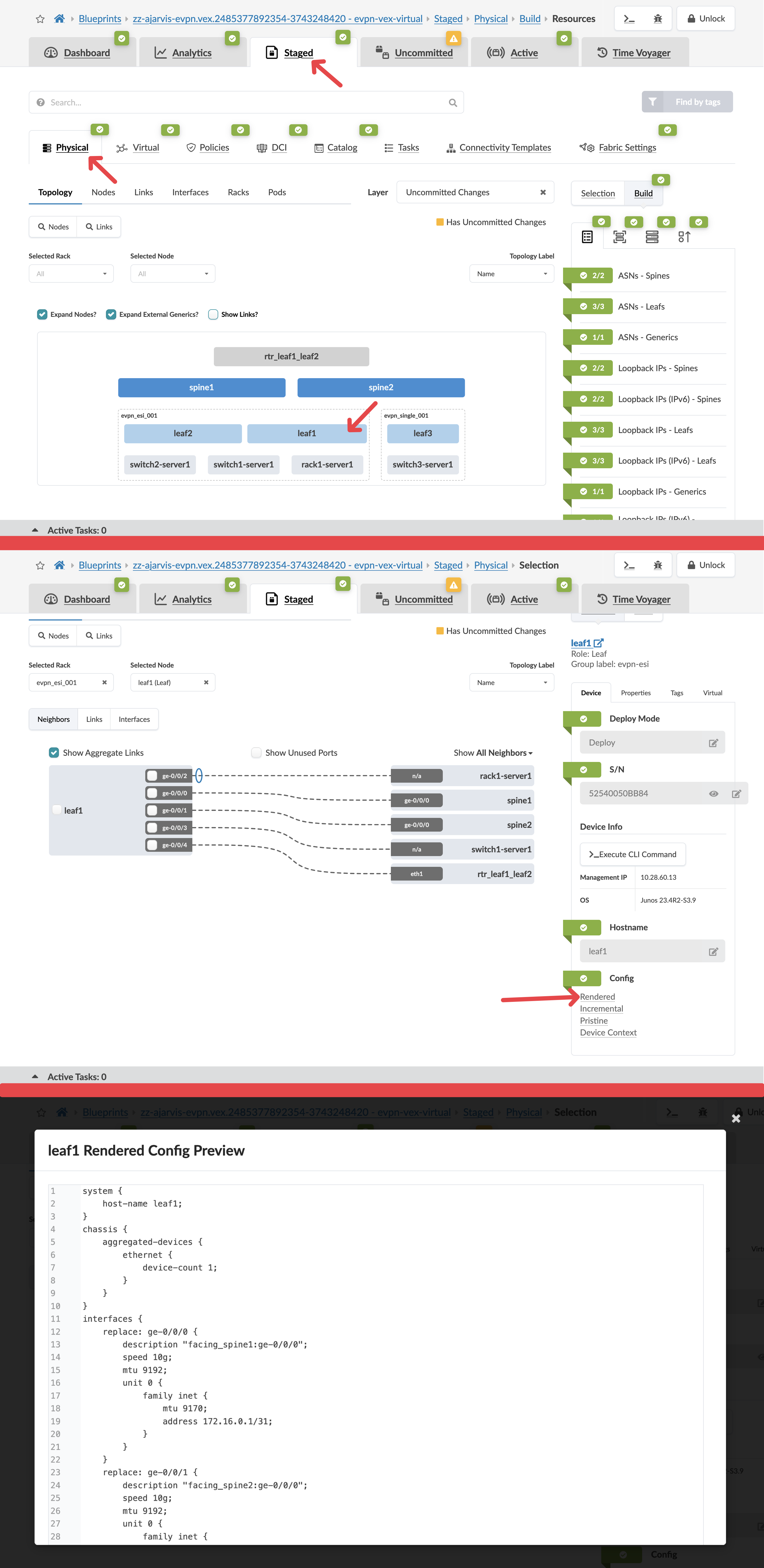
Navigate to Staged > Physical > Topology
-
Select one of your leaf switches by clicking on it
-
Click on the Rendered Configuration tab
-
Scroll through the complete configuration that Apstra has generated automatically:
Take a moment to appreciate what you’re seeing here:
-
A complete, ready-to-deploy device configuration
-
All interface configurations with correct IP addressing
-
BGP underlay configuration with proper ASNs and neighbours
-
EVPN overlay configuration
-
All VRF and routing configurations
-
System settings and management access
All of this was generated automatically based on your intent!
-
-
Notice that you didn’t have to write a single line of this configuration. Apstra translated your high-level intent (rack types, templates, resource assignments) into detailed, vendor-specific configuration.
-
If you’re familiar with network configuration, you’ll recognise that creating this configuration manually would take hours per device and be prone to errors.
This demonstrates the power of Apstra’s intent-based approach. You define what you want your network to do, and Apstra handles all the complex, device-specific implementation details. When your physical devices are connected, this configuration will be pushed to them automatically.
|
Pro Tip: For multi-vendor environments, Apstra generates the appropriate vendor-specific configuration for each device type while maintaining consistent network behaviour. This means you can focus on your design intent rather than worrying about the syntax differences between vendors. |
Exercise 4: Commit Your Blueprint Changes
Now, let’s save all our work with a commit. This records the current state of the blueprint and prepares it for eventual deployment.
-
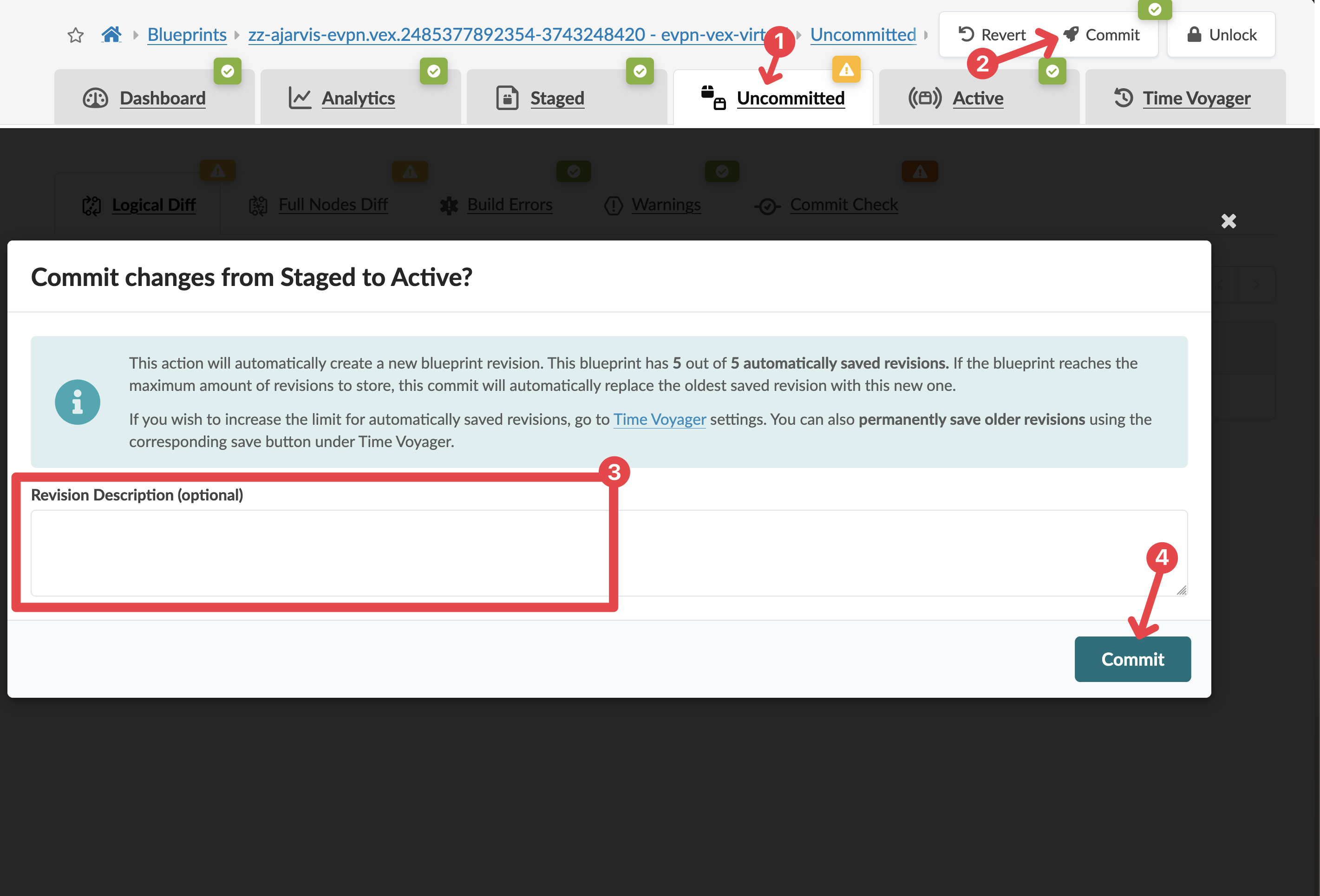
Click the Uncommitted tab to see all staged changes
This view shows the logical difference in the blueprint state since the last commit. Since this is our first commit, it shows everything we’ve added.
You can see even more details by clicking the Full Nodes Diff tab.
-
After reviewing, click the Commit button in the upper right
-
Enter a description for this commit, such as "Initial blueprint creation with resource assignments"
Note: Descriptive commit messages are important for tracking changes, especially when using the Time Voyager feature to move between fabric snapshots.
-
Click Commit to save your changes
What You’ve Accomplished
Congratulations! You’ve now:
-
Created a complete software model of your network design using rack types and templates
-
Instantiated that design as a deployable blueprint
-
Assigned all necessary resources:
-
ASNs for spine and leaf switches from Private-64512-65534
-
Loopback IP addresses from Private-192.168.0.0/16
-
Fabric link IP addresses from Private-172.16.0.0/12
-
-
Made your first blueprint commit to record your work
In a full deployment scenario, you would continue by assigning interface mappings and system IDs, then deploy the blueprint to your physical devices. For this Test Drive, we’ll now switch to an already-deployed blueprint to explore Day 2 operations.
Understanding Resource Assignment
You’ve just experienced one of Apstra’s key capabilities: automated resource management. Here’s why this matters:
-
Eliminate IP conflicts: Apstra ensures no overlapping IP addresses are assigned
-
Simplify planning: No need to maintain complex spreadsheets for IP address management
-
Single source of truth: All resource assignments are tracked and visible in one place
-
Automation: Resources are automatically assigned to new devices as you scale
While we’ve used specific pools in this exercise, Apstra works with any valid addressing scheme. You can create your own pools with addressing that makes sense for your environment, and Apstra will ensure they’re used correctly.
Transition to Day 2 Operations
For the next section of our Test Drive, we’ll be using a pre-configured blueprint called "SE Demo" that represents a fully deployed data centre fabric. This will allow us to focus on the operational aspects of Apstra without going through the complete deployment process.
Let’s take a break here, and when we return, we’ll switch to the SE Demo blueprint to explore Apstra’s powerful Day 2 operational capabilities.