Lab Guide - Resource Allocation in Apstra Freeform
Lab task overview - migrate to resources from property sets
For this lab we will use the 6 stations in the previously built London Underground. This model uses vQFX devices for the nodes along with the associated vQFX Device Profile (to add device context) to represent the stations. As part of this lab exercise, we will migrate this topology from using property sets for its data elements to using Resources and Resource Generators for these data elements. This process will involve setting up the correct components of the Resource Generator framework, creating the Resource Generators and then applying the Resources to the individual Jinja2 Configuration Templates to render the correct configurations using these Resources.
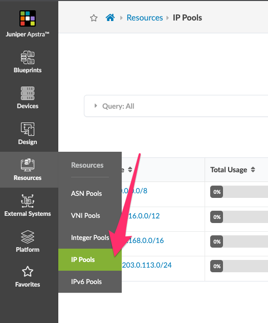
Resource Pools
Resource pools can be accessed from the left hand sidebar of the Juniper Apstra UI. The resources are broken down into resource pool types. These types include:
-
ASN Pools - pools of Autonomous System Numbers
-
VNI Pools - pools of Virtual Network Identifiers
-
Integer Pools - pools of generic integers
-
IP Pools - pools of IPv4 addresses
-
IPv6 Pools - pools of IPv6 addresses
For the changes we will make in this lab, we will be creating two pools: one IP Pool and one ASN Pool.
Create the ASN Pool
Let’s create the first pool we will need, an ASN pool. This pool will be used to allocate AS numbers for bgp neighbor relationships. We could choose are any arbitrary number but to conform to the BGP specification for non-public private-use we will use 4 byte ASNs.
We can see there are several ASN resources already built for us. One of them starts with ASN 42000000. This is the pool we will use.
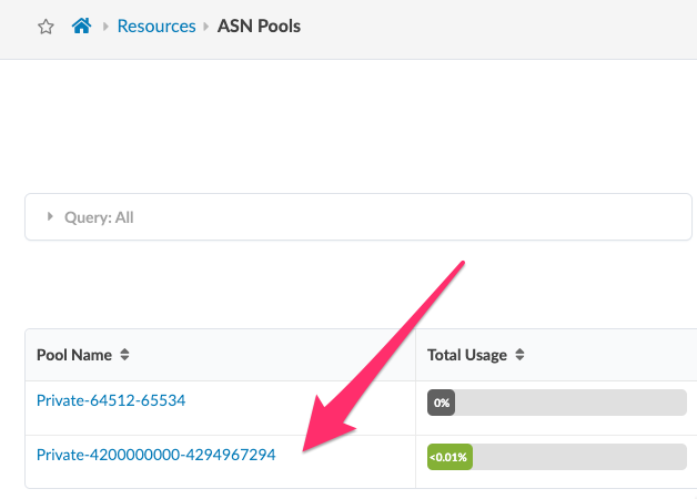
If you need to create additional resource pools this is the location in the UI to complete this task, but since it is already created for us, we will use this existing resource pool in our next step.
Create ASN Pool Allocation Group
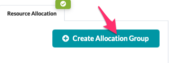
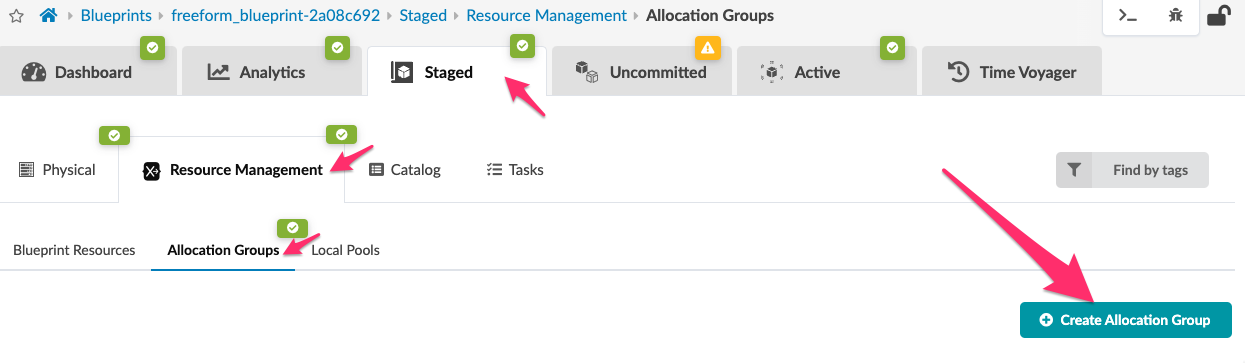
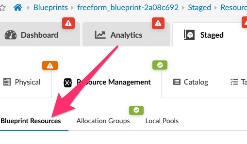
The next step is to create an Allocation Group for this ASN Pool. Navigate to the blueprint staged tab.
-
Navigate to the blueprint pane [Blueprints] > freeform-bp-name > [Staged] tab and on the right hand side you will see a [Create Allocation Group] icon. Click this icon.
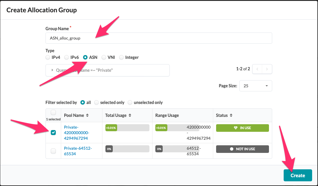
Create allocation group called "ASN_alloc_group"
Now we will use the popup window to create the allocation group with the name "ASN_alloc_group".
Follow the prompts and insert the name "ASN_alloc_group" into the Group Name text box, and then select "ASN" as the Type, select the correct Pool, and finally click create.
Analyze the 'data' property set
Pre-built as part of the lab Blueprint comes a Property set named 'data'. The contents of this property set have been used to assign ASNs and Loopback IPs to the Blueprint. We will use this property set to assist with modelling the required Resource Allocation Groups and resources. Click on the 'data' Property Set by navigating to [Staged] / [Catalog] / [Property Sets]. The Property Set will open to reveal the index or key as the System Name. Under each system there are two elements:
-
an ASN Number
-
a loopback address
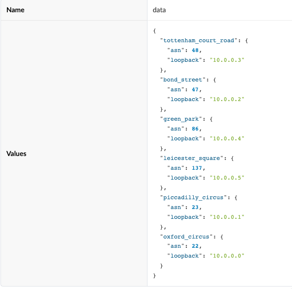
These values are statically defined by the user, to be later utilized or assigned in a Jinja2 Configuration Template. Using Resource Generators we can dynamically generate the same resources, as well as Link IPs (/31 addresses) for the links between systems (switches).
As previously mentioned, the 'data' Property Set was designed for use within this lab. You will now configure a Resource Generator to accomplish the same goal, in this case we will be pulling the resources and assigning them from a user-defined Pool. Consider that as you add more systems in the future, Resource Allocation will allocate these resources for you automatically. This also helps keep the property sets from being subject to fat-fingering/human error.
To set this up we will perform the following tasks:
-
Clear the IP addresses from the interfaces
-
Create a Resource Generator for the link ip addresses.
-
Create a Group Generator to create a group for each system.
-
Create a ASN generator to generate one ASN per system.
-
Create a loopback generator to generate one Loopback IP per system.
Once these tasks are complete the next phase of the project begins where we use the resources to render the configurations by modifying the Jinja2 config templates from using property sets to resources. To accomplish this we will complete the following tasks:
-
Modify Jinja2 for the system loopback address
-
Modify Jinja2 for the system ASN number
Clear IP addresses for the point to point interfaces
Let’s get started by first opening the Cabling Map Editor and removing the IP addresses from the interfaces. We do this so that we do not get conflicts from the original topology.
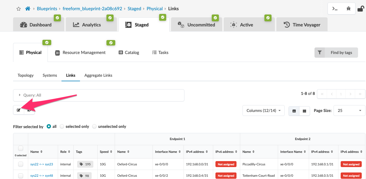
This will then open the Cabling Map editor screen, and you should see something similar to this:
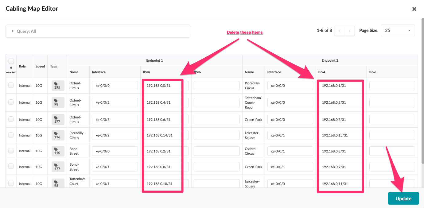
Now, clear the IP addresses highlighted in the red boxes and then click the Update icon.
Be careful not to remove system or interface names during this step
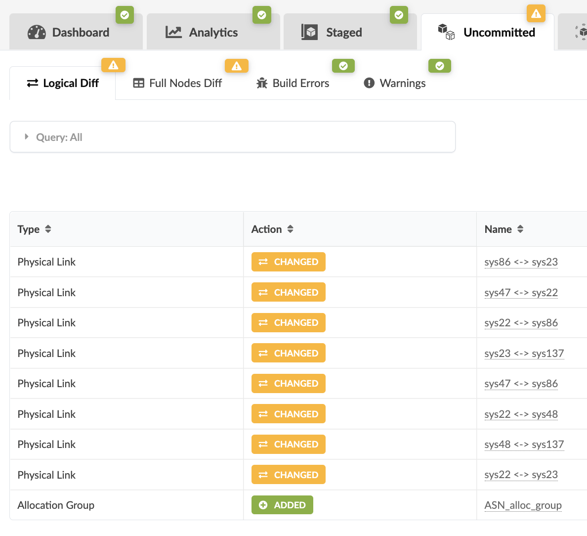
Once completed, you can view the Uncommitted changes in the [Uncommitted] tab as shown below
Resource Management for Point-to-Point IP links
We will now create the resources needed for the Point-to-Point IP links. You may have noticed from the previous step that /31 IP addresses had been assigned from the 192.168/16 subnet. Navigate to [Resources] > [IP Pools] in the main UI menu on the left hand side to view this Resource Pool already created with the 192.168/16 range.
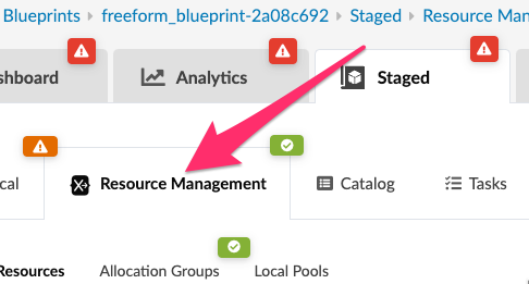
Resource Management Tab
Most of the activities in the next sections will be completed in the [Staged] > [Resource Management] tab; an area that will be a major focus of learning as we progress through this lab.
Allocation group for IP links.
The next step will be to create an 'Allocation Group' for the links between the systems, allocating the resource values from the chosen IP pool. This can be achieved in the [Staged] > [Resource Management] > [Allocation Groups] tab, as well as the [Staged] > [Physical] tab.
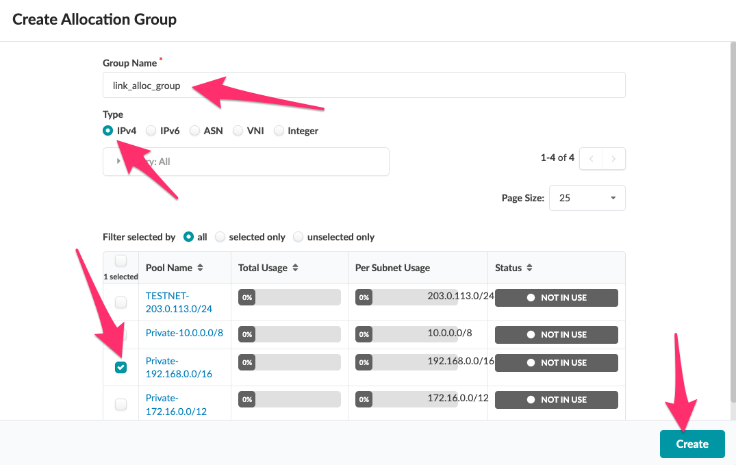
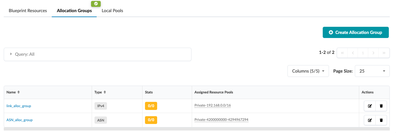
Name the new Allocation Group "link_alloc_group", select the IPv4 type and assign the IPv4 Pool Private-192.168.0.0/16. Finally, Click on the [+ Create] icon.
You should now see the resulting allocation group called "link_alloc_group", alongside the asn_alloc_group created earlier. Neither one of these Allocation Groups have been assigned to a Group, so the 'Stats' column will indicate ![]() as shown below.
as shown below.
Create a Resource Group and Resource Generator for the IP links.
Let’s now create the Resource Generator for the IP links.
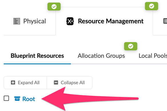
Here we will see that we have a tree like structure with just the root of the tree.
We will create a Group first, and inside that group we will then create the Link IP Resource Generator. This Resource Generator will utilize a graph query to the backend graph database to select the links from the topology and create a link IP endpoint resource for each link we find. This is dynamic in nature so if an additional link or set of links is created in the topology, it will identify the new links and create IP addresses and assign them to the link data structures in the graph database.
| Why would you ever need more than one group? Groups are used like folders to group together resources and Resource Generators. There is one Group already allocated for you which is the "Root" group. This group is the Group that holds all other groups (the Root of the folder tree). You cannot create resources in the Root group so you must create a group (a folder) in Root first. Once you have added new group under the "Root" group you will then be able to create and assign all the resources necessary. |
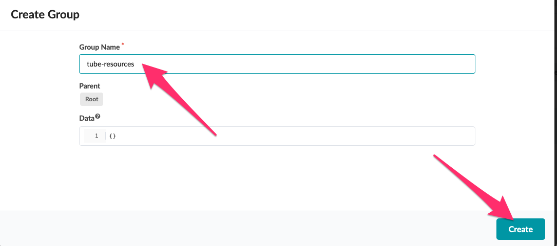
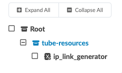
Create a Resource Group called "tube-resources"
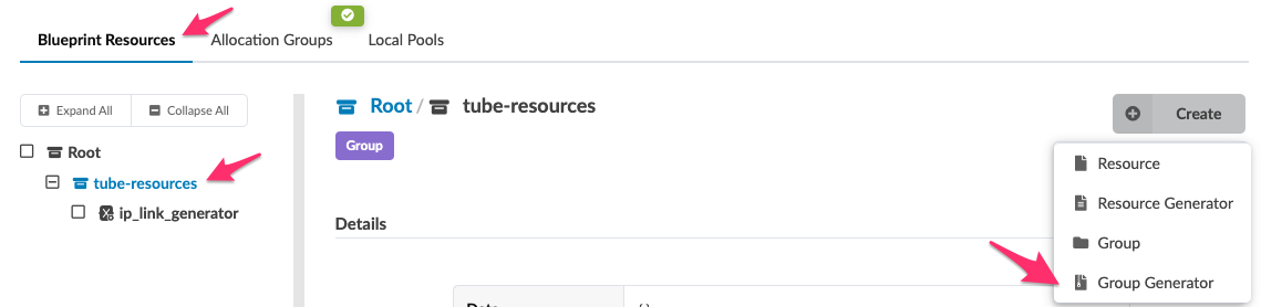
Click ![]() on the far right of the screen and select 'Group'.
on the far right of the screen and select 'Group'.
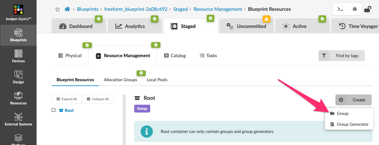
Once you have the create dialog open, fill in the Group Name with "tube-resources", leave the "Data" field blank at this time and click the "Create" icon. Notice that the Parent by default is the 'Root' of the folder structure.
| We missed out the "Data" field; what is it for? It is meta-data that you can associate with the Group. Meta-data is used to impart information to the object you have created. It may be used for things like a description or perhaps indicate to others what the object represents. |
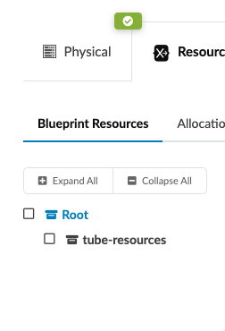
The resource allocation tree should now update showing the new group:
Now select that new resource Group 'tube-resources' and create a Resource Generator for it:
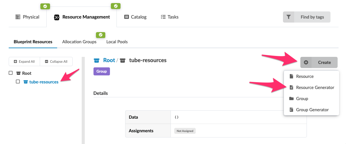
Create a Resource Generator called "ip_link_generator"
-
Select tube-resources under the Root folder, click on
 (far right) and select Resource Generator
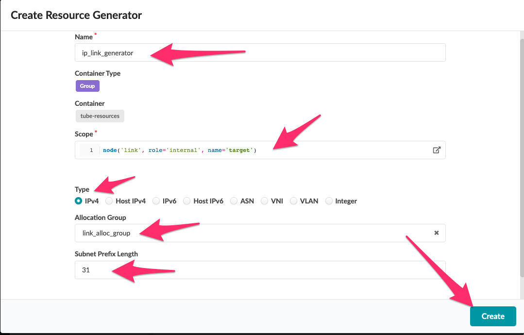
Name the new Resource Generator "ip_link_generator".
For the Scope entry we will use a graph query to find the link nodes of the graph.
Let’s use this graph query which will select all the links that have the role of "internal"
node('link', role='internal', name='target'), This selects all internal (fabric facing) links only. This is the graph scope for this Resource Generator. You can copy this and insert it into the Scope area. Next, select IPv4 for the Type, and then select the "link_alloc_group" for Allocation Group and finally insert a 31 as the Subnet Prefix Length
You should now see that a number of resources have been created and the resources tree is now populated with a new Resource Generator.
A link is a node in the Apstra GraphDB, so we can use a very simple graph query here to pull the link nodes from the database. A very important element is name='target' for without this nothing will work, so please don’t forget it! Take a look at the Apstra Documentation on Graph it should help you to create other useful graph queries, you may also find some examples useful we use in the lab for other Resource Generators.
|
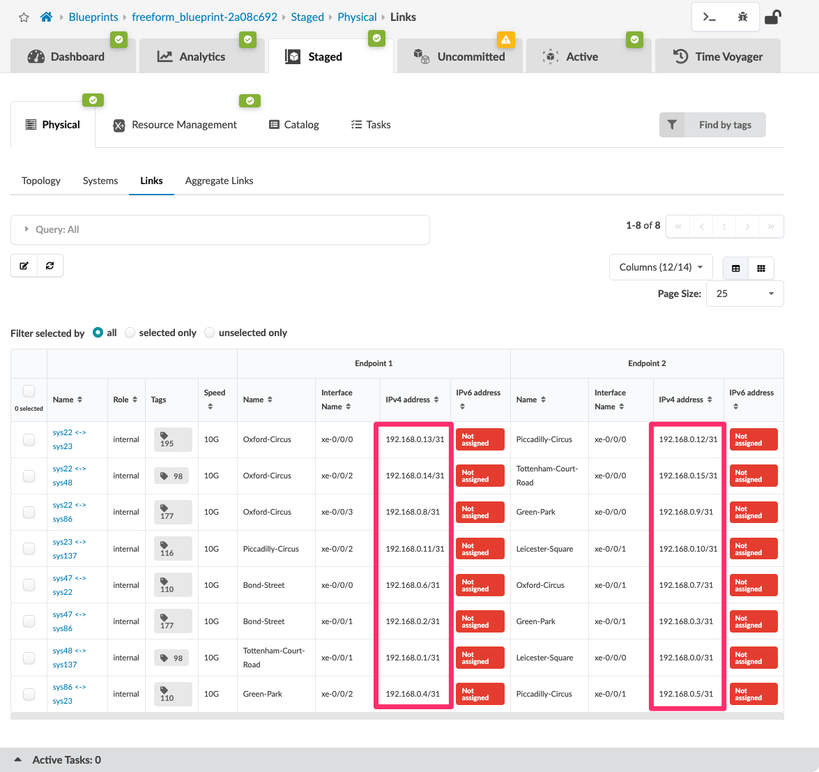
Let’s review the link IPs that have been generated and see that they are assigned to the links.
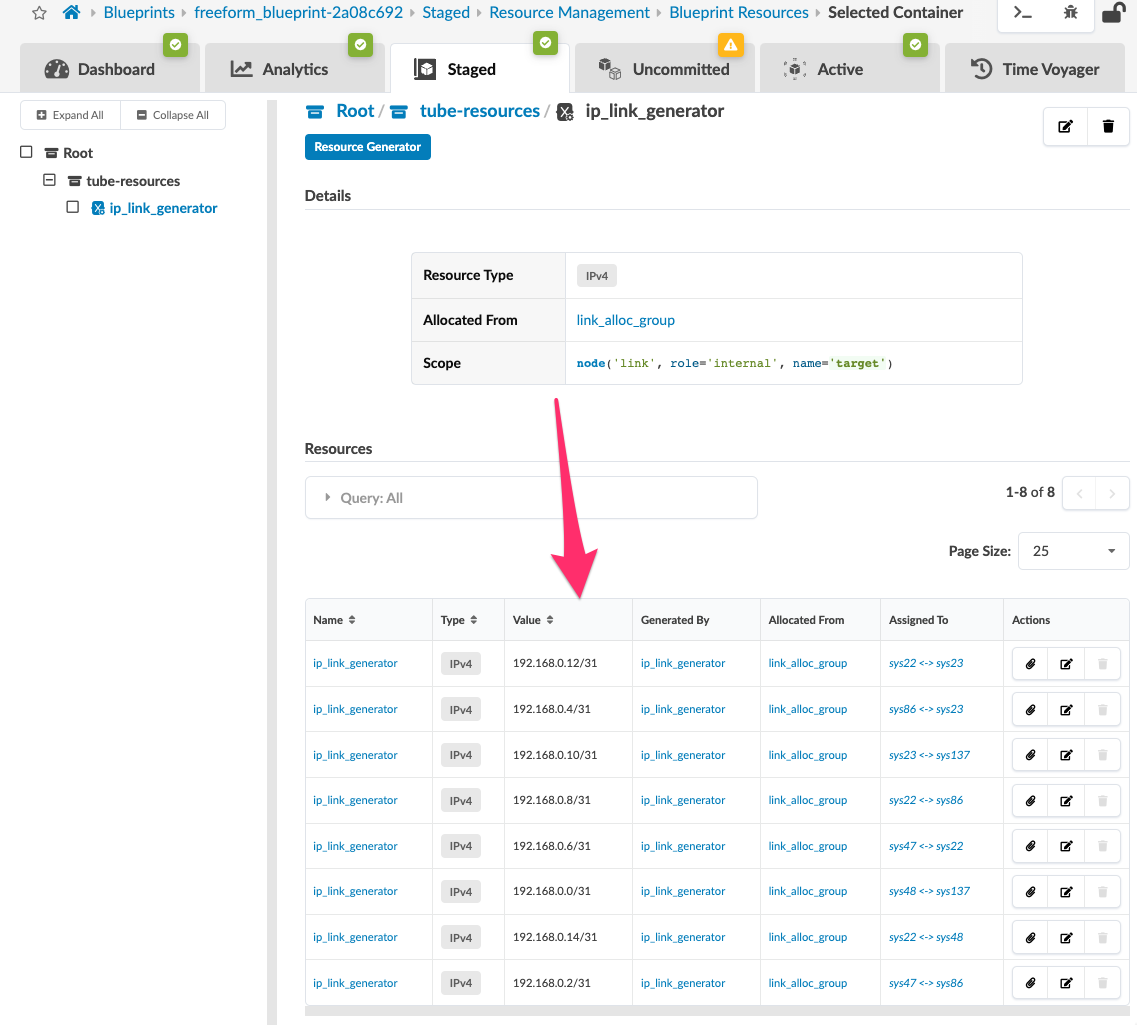
As you can see the Scope generated a resource for each link in the topology, defined by the GraphDB scope. Take a look at the actual links to see if IP addresses are assigned correctly:
Create a group generator to create a group for each system.
Next we will extend our framework to introduce the concept of a Group Generator, which will be used to create and group resources for each system in the topology.
Group Generators do as their descriptions says: they generate groups dynamically to help us more easily manage resources. These dynamically created groups are created based on a graph query scope, as in the previous exercise with Resource Generators where we used the graph query node('link', role='internal', name='target') to pull the internal ip_link nodes from the database.In this example, we will focus on managing the resources for each system, including a Loopback IP address and an ASN number for BGP peering. To accomplish this, we will use a scope graph query to return all the systems and create a Group (folder structure) for each system. This way the Loopback IP and ASN for the systems declared in GraphDB are grouped together by system name! Sounds logical! |
Do we need these groups?
Not from a functionality perspective, but as you grow your deployment into a larger and more complex design, it can be difficult to find and manage all the various resources.
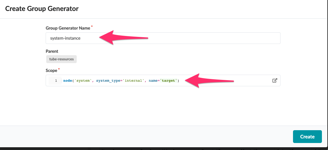
Create the group generator to identify each system.
-
Name the group generator
'systems' -
Use the Scope
node('system', system_type='internal', name='target') -
Click the [Create] icon
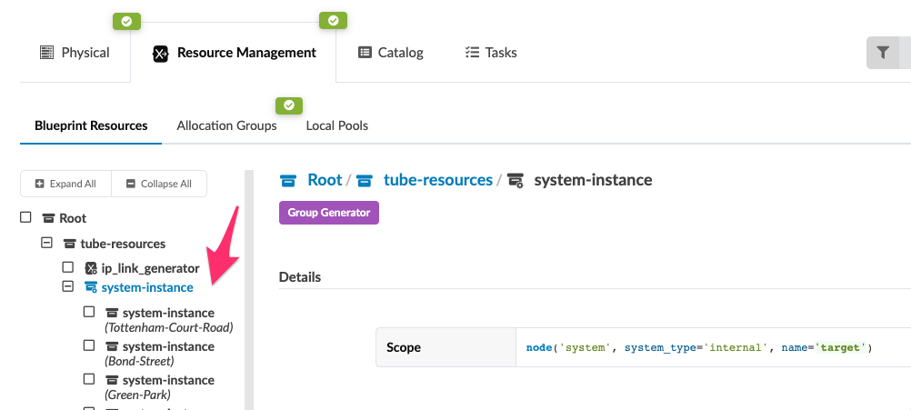
The result of this is that you should immediately see a new folder structure that includes each system output from the Group Generator graphDB scope
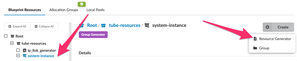
Create two Resource Generators for the ASN and the Loopback IP utilizing the group generator.
Now we have the folder structure for each system, we can move on to the exciting part of creating the system based Resource Generators:
-
ASN generator called "asn_generator"
-
Loopback generator called "loopback_generator"
-
Name the instance "asn_generator"
-
Set the instance type to "ASN"
-
Set the allocation group to "ASN_alloc_group"
-
click the Create Icon
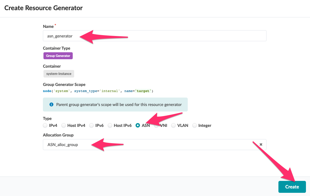
| notice the Scope is already set and inherited from the Group Generator, saving us time and reducing the chance for human error! |
Repeat this again for the Loopback IP generator:
-
Navigate to Staged → Resource Management → Allocations Groups
-
Click Create Allocation Group
-
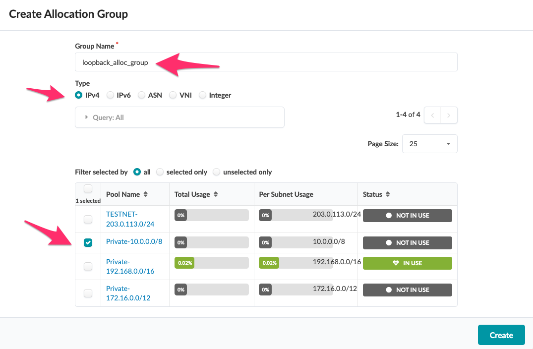
Create an IP allocation group called "loopback_alloc_group"
-
Use the name "loopback_alloc_group"
-
Select the "Private-10.0.0.0/8" for the IP pool you will use
-
-
Return to Blueprint Resources
-
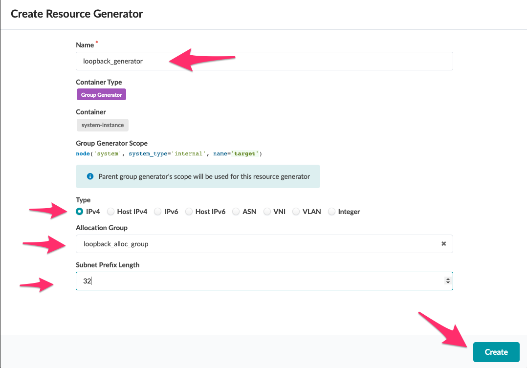
Create a Resource Generator under the 'system' group in the Blueprint Resources Root tree, by selecting 'system-instance'. As you did above, Click on [+ Create] and select [Resource Generator]
-
Name the instance "loopback_generator"
-
Set the type to IPv4
-
Set the Allocation Group to "loopback_alloc_group"
-
Set the Subnet Prefix Length to "32"
-
click [Create]
-
Congratulations. You have created 2 resources per system, one ASN and one Loopback IP! Alongside the resources for the IP links, we can move on to the next step which is to modify the Jinja2 Configuration Template to use these elements rather than the 'data' Property Set used previously.