Lab Guide - Apstra Freeform
Freeform Blueprints
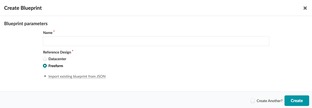
When creating a new network topology with the Freeform reference design, you start by creating a Blueprint. As with the Intent-based DC reference designs, the Blueprint contains all Apstra-managed elements required to manage or operate a network. There are key differences in how Blueprints are structured and used in Freeform, as compared to the DC reference designs. The DC reference designs require design elements such as logical devices, interface maps, racks, and templates. These abstractions are not used in a Freeform design because configuration detail and device links are created directly within the Blueprint. The exercises in this lab leverage a Blueprint that has already been created for you. When creating a new Freeform Blueprint, you start by selecting 'Freeform' in the Create Blueprint dialog, as shown.
Inspecting the pre-prepared Freeform Blueprint
Let’s investigate the Blueprint that is provided for this lab. When you click on the Blueprint you will be presented with a complete topology that we will modify by using the Topology Editor.
As described previously, the Topology is a collection of objects that represent the systems and links that describe the network you want to build. Details for each object are stored in GraphDB and provide the contextual basis for each element within the system. These elements are:
-
Defined during the Design phase to build out configuration
-
Used during the Operate phase to provide meaning to the telemetry data
Device Profiles in Freeform
Device Profiles define the capabilities and characteristics of a supported hardware device in the Apstra system. The Device Profile provides specific contextual information we can use during the design phase such as:
-
Port count
-
Port speed
-
Which ports can be channelized
-
The total number of ports the ASIC combined with the front panel will support
-
The NOS version tested & validated by Apstra engineering
| In the initial release of Freeform, only Juniper switches and Juniper Device profiles are supported. |
Review an existing Device Profile
Device profiles must be first imported into a Freeform Blueprint before pre-staging can begin. This has already been completed in your lab environment. The navigation menu on the left side is where Device Profiles are searchable and viewable. Let’s take a look at the available Blueprints stored there.
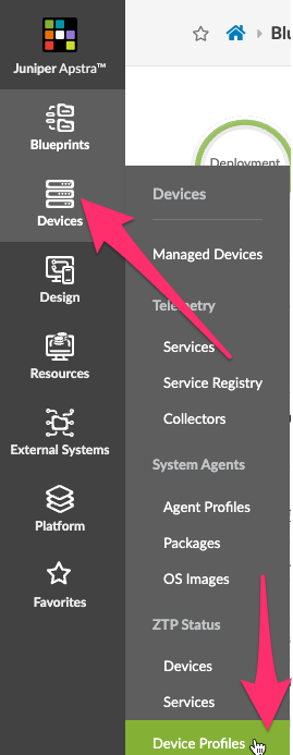
Clicking Device Profiles from this menu will result in displaying the entire catalog of devices. We mentioned in an earlier note that Freeform will initially support just Juniper switches, so let’s narrow the list to usable devices via the Query function on this page.

We now see a list of Juniper devices as shown below.
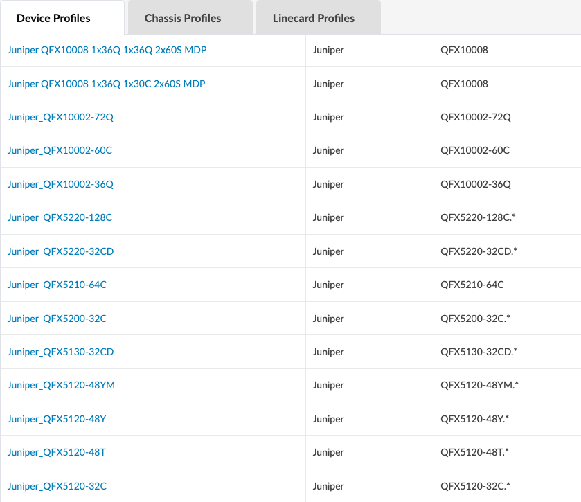
We will now move in the UI to the location where we can view the vEX device already present in our Blueprint. Click the device name in the list to view the current Device Profiles:
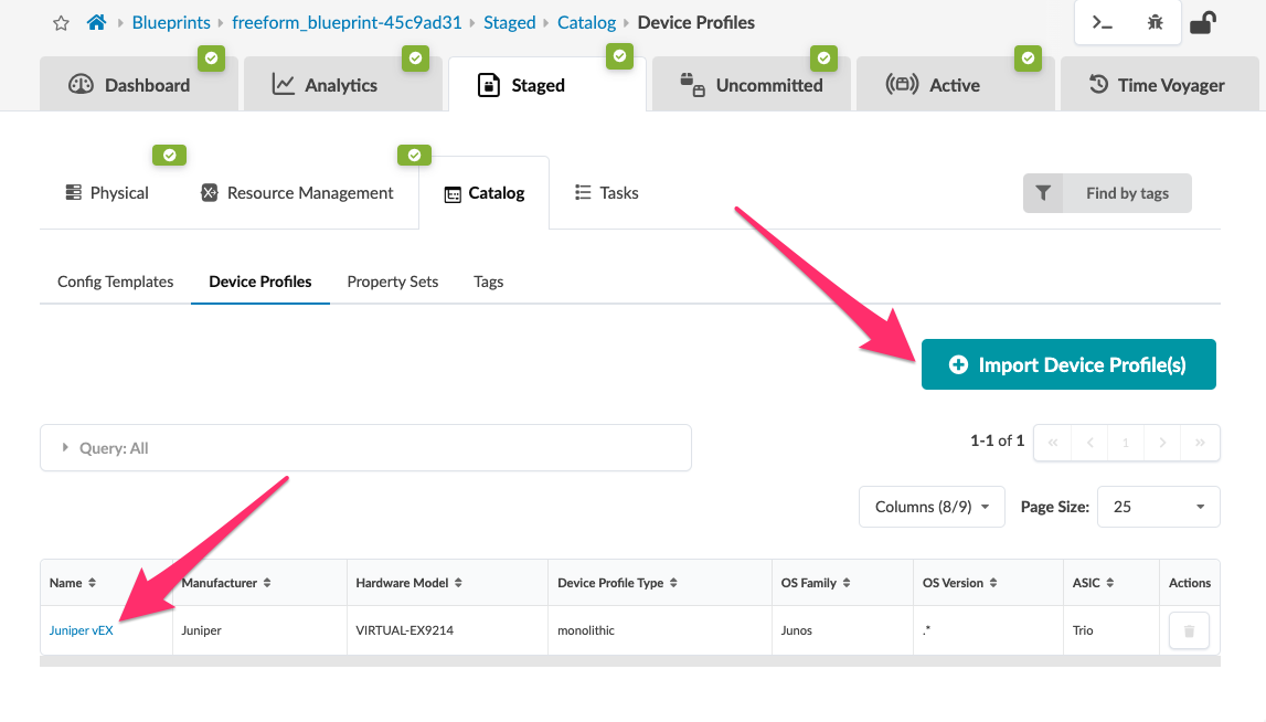
Take note that any supported Juniper Device Profile can be imported here. When selecting + Import Device Profiles(s) you will be presented with a Juniper Device Profile only list.
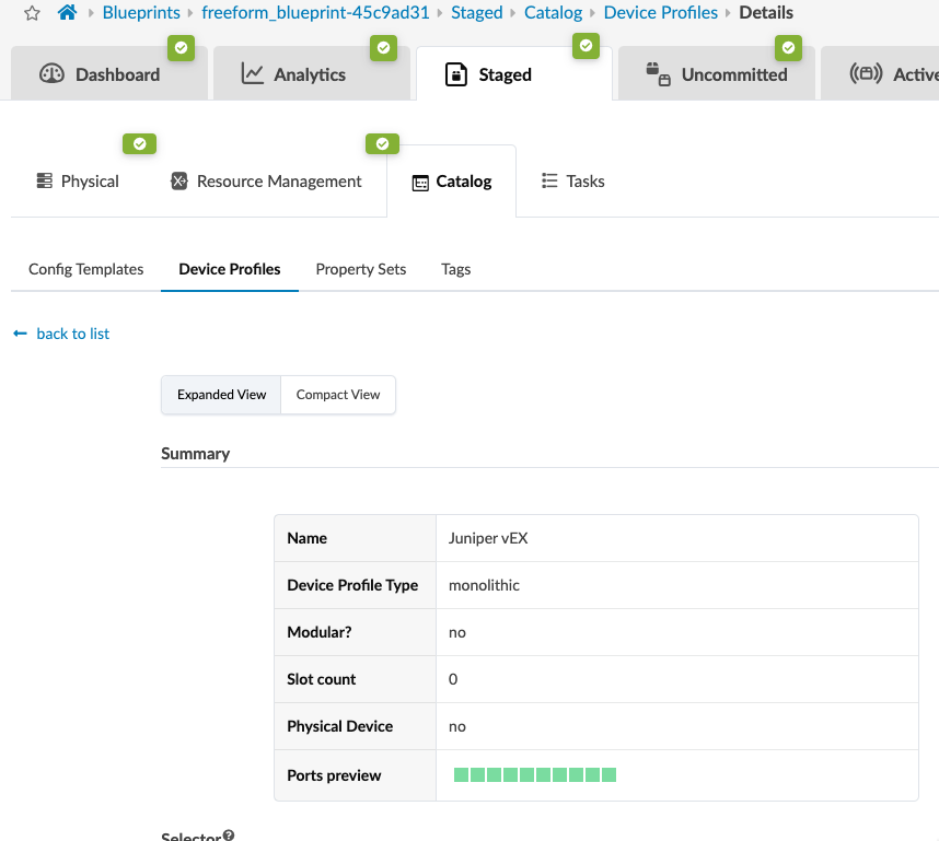
Clicking the name (Juniper vEX) reveals the details about this particular device profile. From an Apstra perspective, you could describe the Device Profile as the single source of truth for a specific device. This level of knowledge is key to the embedded contextual validation capabilities provided by this solution.
Topology Editor
The Freeform Blueprint in your lab already contains an existing network topology. This is done to accelerate the process of becoming familiar with the power and flexibility delivered by Freeform. As with all Apstra reference designs, pre-stage configuration work will be undertaken within the Staged tab.
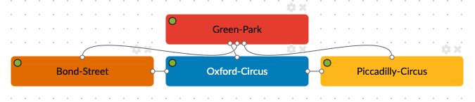
This is the section of the London Underground that we use for our reference.
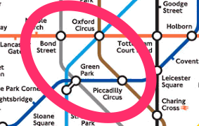
The Topology Editor reflects the stations and how they interconnect, as shown in the underground map above.
View objects
To illustrate how this was built, we will use the Topology Editor. With it, we are able to create bespoke network designs based on any set of Junos switch capabilities in which the switch itself is supported by Juniper Apstra (has an associated Device Profile). We can choose to add devices that are internal to our management realm or external, i.e. not managed by Apstra.
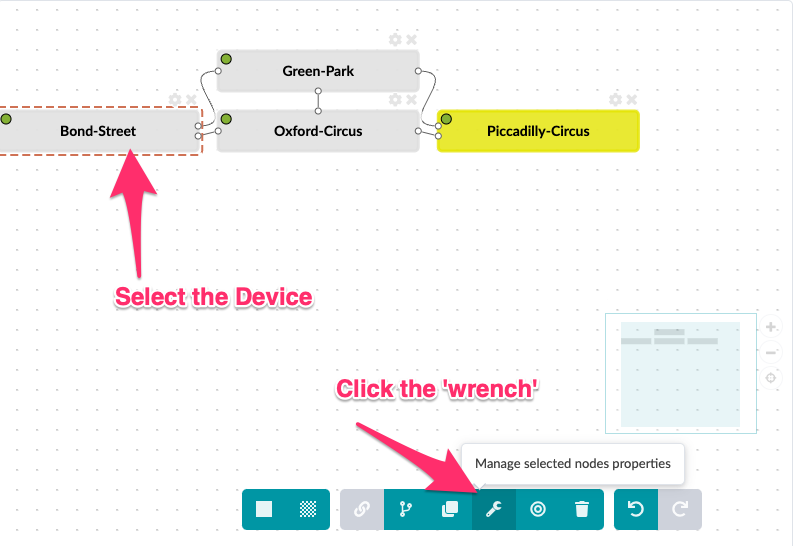
When the objects were created, several parameters were set, including the System name (Label). Let’s examine these attributes by putting the Topology Editor in Edit Mode by selecting

Color objects
New systems default to a grey color when added to a topology. To highlight a different system in your topology, each can be assigned a specific color while in edit mode.
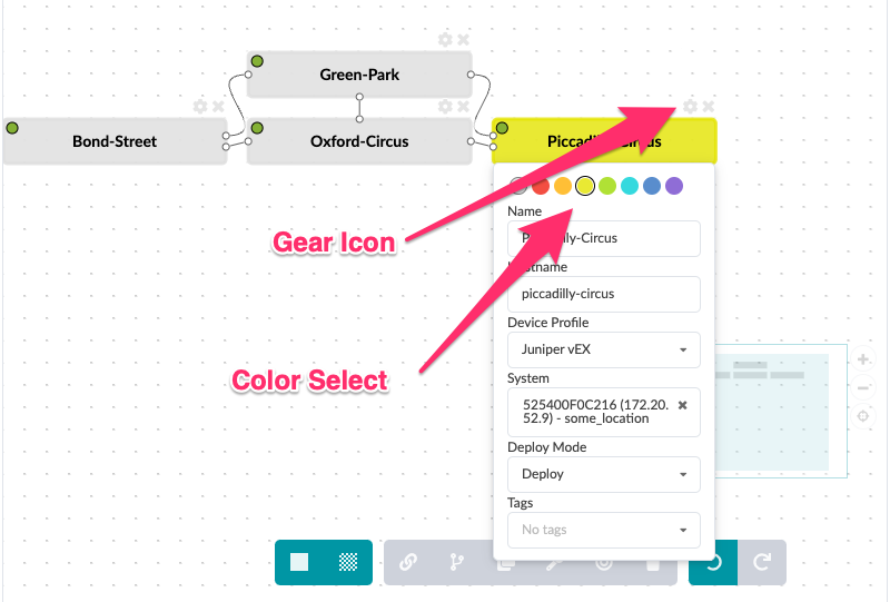
The same can also be achieved by selecting the node and clicking the wrench icon.
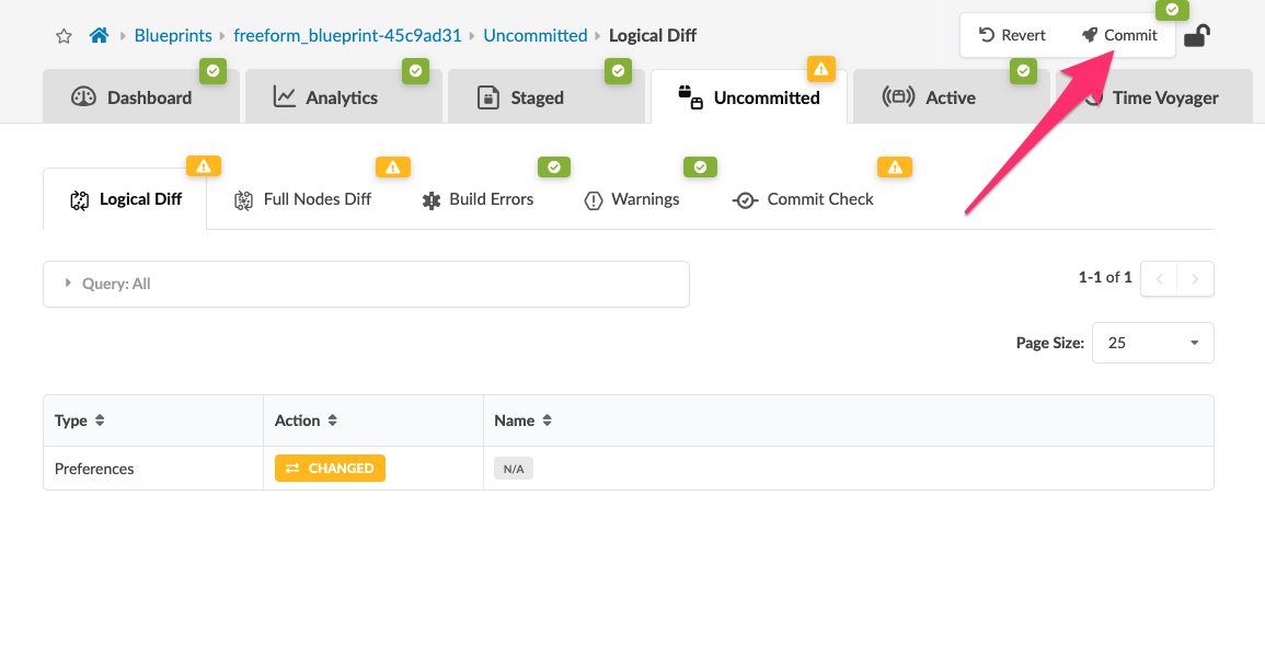
Once you have completed editing the Label and changing the node color, you will need to navigate to the Uncommitted tab in the Blueprint. In the upper right, you will see the Commit button. Click this button to apply the staged changes to GraphDB.
|
Multi-Select objects and other shortcuts
Selecting multiple systems simultaneously can sometimes be a challenge. Here are some tips for using the topology editor.
|
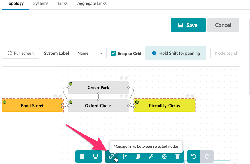
Link objects
Let’s add a new link between Bond-Street and Piccadilly-Circus.
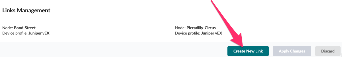
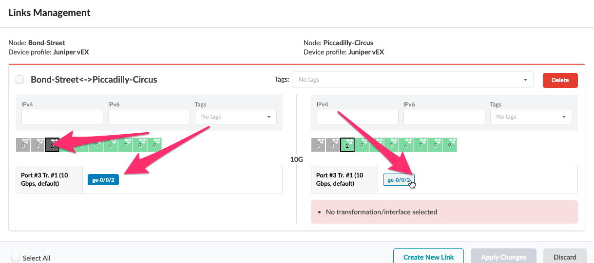
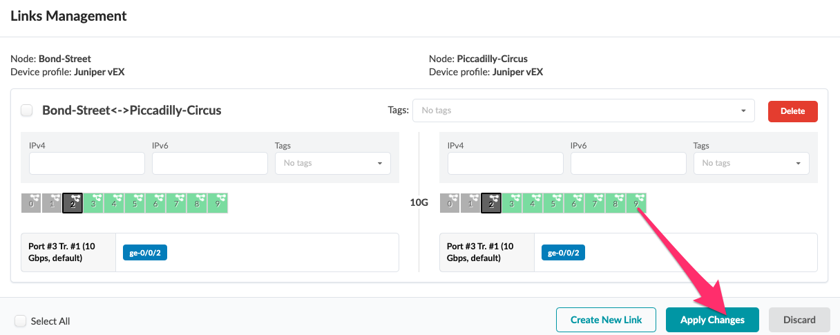
-
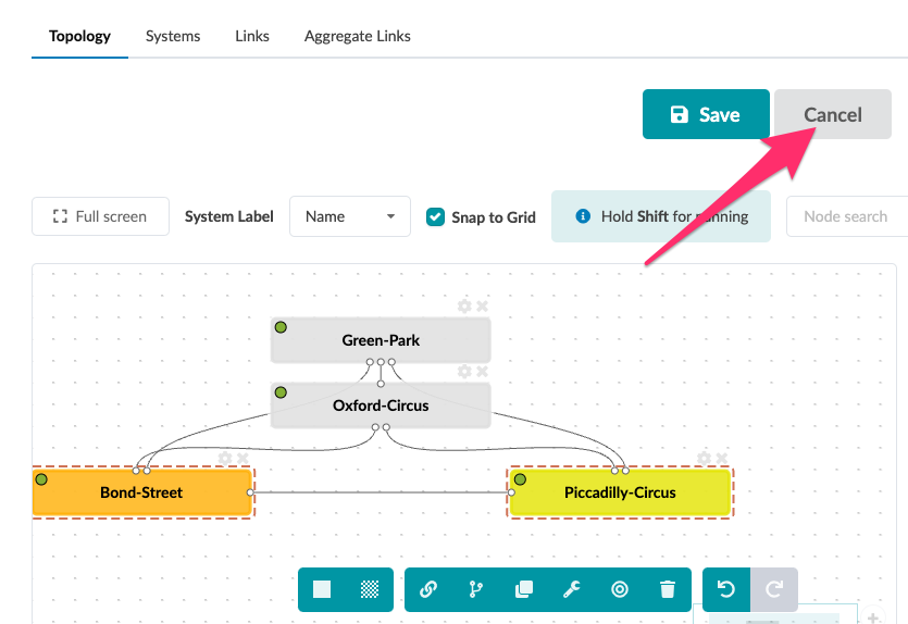
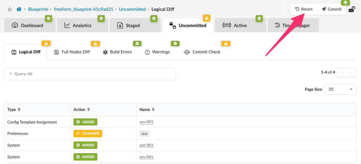
Once you have done this and understand how this works, you can use the Cancel button to back out of creating the link. If you save the link, the change will be staged in the Uncommitted tab. Click Revert as shown below to clear the link from being created in the topology. For the purpose of this lab, this Bond Street ←→ Piccadilly Circus link is not needed and will generate anomalies if it is committed to the Blueprint. Once the change has been cancelled or reverted, you should see evey icon in the Blueprint colored green i.e. no uncommitted changes.
or
Tags
In Apstra, tags are a powerful feature that allow metadata to be assigned to nodes (switches / links etc). They are useful in identifying, organizing, searching and filtering objects in the Apstra UI. They are also helpful in categorizing resources by purpose, owner, environment, application or other criteria. Tags are metadata and are useful for more than labeling objects. They are also applied as a node property in the graphDB. These properties are available for use in referencing their attached objects in other types of operations. One example is using tags in Jinja to populate dynamic variables during config generation. Another is using tags to reference related systems or links in an Intent-based Analytics operation.
For example, you can use tag firewall to render a specific description
{% if has_tag(interface.link.neighbor_system.id, 'firewall') %}
	 description "this is a firewall facing interface";
{% endif %}
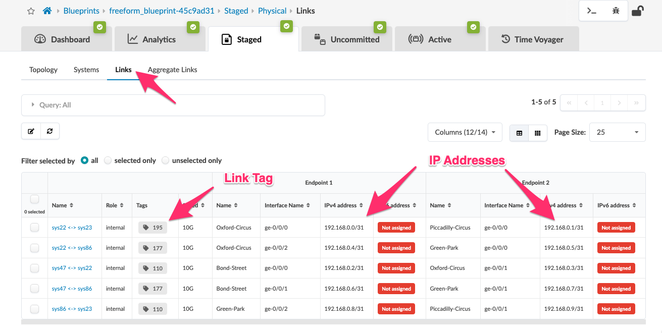
View links between stations & their parameters
We now want to view the details of the links between our devices. Links can have properties assigned to them that include IP addresses and tags. Let’s view these properties that have already been assigned.
View IP Addresses of links/systems.
Let’s confirm a few IP addresses that have been assigned for topology objects and then view them in the device context.
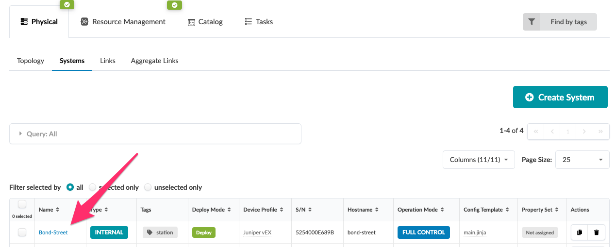
Let’s then look at the device Oxford-Circus to confirm the links are properly configured with IP addresses.
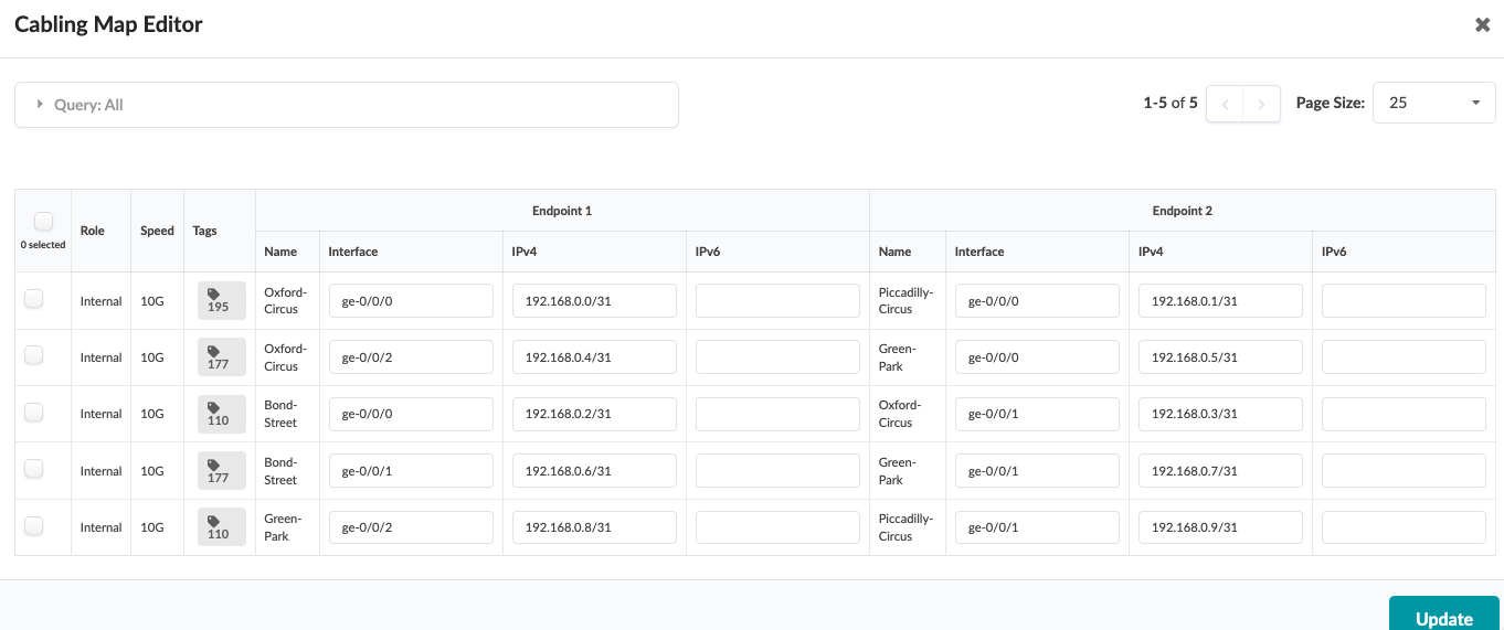
View the cabling map
If we click on the Edit icon for the cabling map in the Links view, we can see that we can quickly and easily modify interface and IP addresses for the links all at once.
![]()
Clicking on the first link will open up a new UI where the interface names and IP addresses can be manually modified as required.
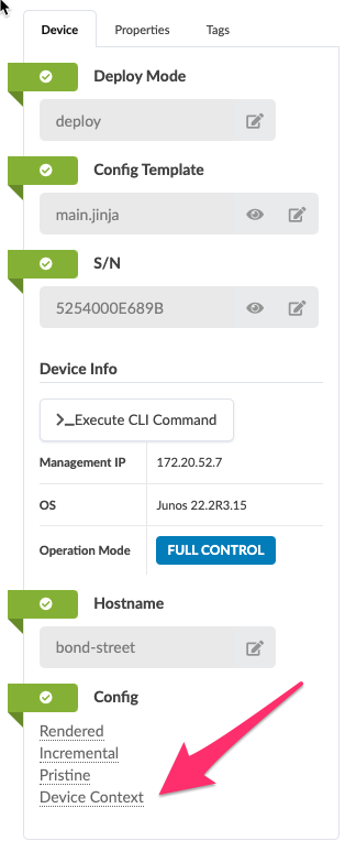
View the device context data.
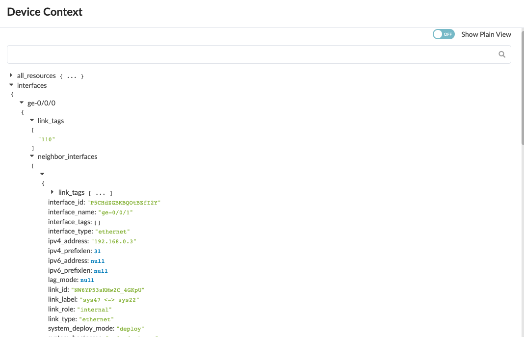
Now let’s take a look at the device context and view the links in the data model.
Recall that our topology has a link from Bond-Street to Oxford-Circus as shown:
 Interface
 ge-0/0/0 is connected to Oxford-Circus’s ge-0/0/1
Expanding the tree reveals the context that can be accessed via a Jinja based Config Template to assist with rendering accurate Junos configurations. Later, we will use some of this information seen in the Device Context to dynamically generate a login banner that contains neighbor information upon login. This is a small illustration of what can be done with system attributes in a Freeform Blueprint.
Internal and External System Objects
Internal systems under Freeform management must have a Device Profile assigned to them to make their attributes accessible and to provide context to device agents. External systems are not under Apstra management, but they help provide context of how the managed system will connect. An External system has attributes that Apstra uses to configure links from Internal systems. They do not have agents and their configurations are not managed by Apstra.
External system icons are differentiated from those of Internal systems as shown below.
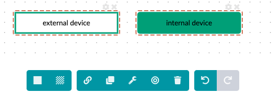
Please see below for a brief explanation of all icons in the Topology Editor.
![]()
Now revert this change when done so future sections will complete successfully.