Lab Guide - Apstra Freeform
Estimated Time: 60 minutes.
| It is recommended that users complete the previous Apstra labs to gain familiarity before attempting the Freeform lab. |
Log into CloudLabs
-
Access the Apstra virtual environment with the CloudLabs portal URL that was emailed to you. For best performance, use the latest version of Google Chrome or Mozilla FireFox web browsers.
-
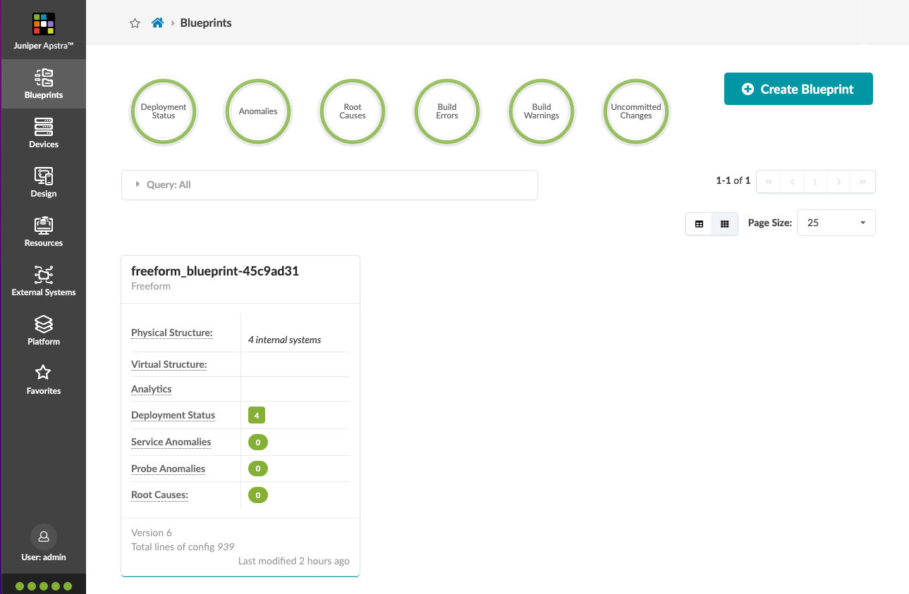
It can take about twenty minutes for the topology to be provisioned. In the meantime, the status shows as DEPLOYINPROGRESS and the button for accessing the AOS UI is not functional. When the status changes to UP and the button becomes functional, click Open in a New Tab to access the Apstra web interface.
-
If a security warning appears, click through to proceed to the site (click Advanced, then click Proceed to <aos-server-ip> (unsafe)). The warning occurs because the SSL certificate that was generated during installation is self-signed.
-
Log into the server with username
adminand the password provided in the portal (above the Open in a New Tab button).
Introduction to Apstra Freeform
Freeform is the latest addition to the available reference designs from Apstra. It differs from the existing DC reference design model in that control of all design elements is placed entirely in the architect’s hands, meaning you now have the choice of both topology and protocol deployed in your environment. Therefore, networks designed with Freeform are not restricted to the design framework that exists in the existing data center reference designs, i.e. eBGP / VXLAN / EVPN / ERB. However, the value proposition of Freeform is that it can still leverage key components of the solution to provide contextual validation when designing your solution. It is important to note that having unlimited design flexibility comes with inevitable tradeoffs, primarily around the abstracted and automated user experience.
A Freeform reference design differs from the other reference designs in that the network designer is responsible for creating and validating all device configurations. As a comparison, the primary difference between Ansible and Freeform, is that Freeform provides built-in contextual validation to assist with building a valid Junos / Junos Evolved configuration. Any feature, protocol, or architecture that fits the deployment scenario can be leveraged, as long as it conforms to the protocols supported by Junos / Junos Evolved as well as the Juniper switches and NOS versions supported and validated by Apstra.
Apstra Components
At a high level, the components used in all Apstra systems are as follows:
-
Device Profiles - Adds device specific context
-
GraphDB - Stores the interconnected relationships of the topology
-
Property Sets - Stores data sets to be used in device configs (ASN / IPs / VLAN IDs / Tags etc.)
-
Config Templates to build the switch configuration:
-
In the DC reference design these are hidden as part of the Intent Based solution and also pre-validated for eBGP / VXLAN / EVPN / ERB etc.
-
In Freeform, these are exposed to you the user, where you can use the Device Profile, GraphDB, Property Sets and the 3-pane editor (discussed below) to build your desired config.
-
-
Tags - used to highlight aspects of the system you’d like to target with specific config or analytics
-
Offline pre-staging - You can design & build your future network without a single physical switch present
As with the Intent based DC reference design, Freeform leverages the graph context, as well as Intent-Based Analytics (IBA), configuration validation, NOS management, Time Voyager (rollback), and numerous other Apstra software features to assist in your DC management. When compared to the Intent Based DC reference designs, the high-level trade-offs for greater design flexibilty is increased complexity and a reduction in depth of IBA capabilities.
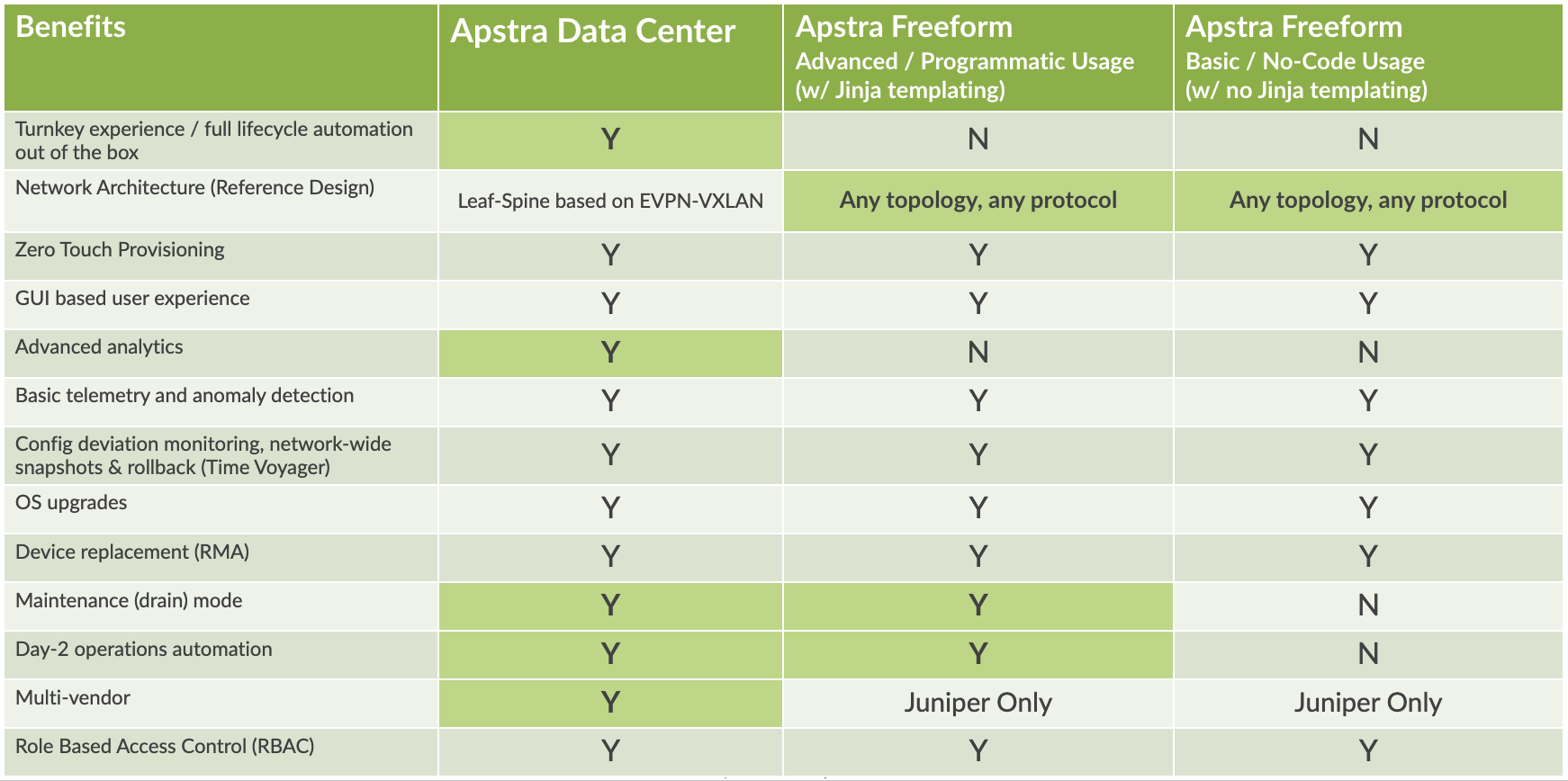
Please see the table below for a quick comparison of the Apstra DC reference design vs. Freeform. Take note that Freeform could be used with a flat file i.e. without Jinja2 templating. This would allow you to leverage the power of Software Defined Networking with Freeform without starting from the beginning, i.e. you could copy / paste your existing network config into Freeform as a base to start automating.
Freeform consists of various design, build, deploy and view elements to manage specific network design aspects. Their function and usage are described in the following sections where we will introduce some example models for building an arbitrary network topology.
London Underground Network Model
An interesting network to model is a subway or underground rail system, where each station (node) is connected to another via a track (link). There is a known distance and multiple available routes between stations both of which can be quantified in a network diagram (within Freeform in this example). As we go through this example, we will use all of the component parts of Freeform as described here.
For this lab we will use the 4 stations in the London Underground as a framework for a small network. This model uses vQFX devices for the nodes along with the associated vQFX Device Profile (to add context) to represent the stations. We will connect links between each node (station) in the Topology Editor to represent the train lines to other stations. This, as mentioned previously will add further context to our model, i.e. the relationship between the nodes. Using an advanced routing protocol allows the systems to determine the available routes and which path has the shortest latency between source and destination stations. In this example, we have chosen eBGP to determine the multiple available routes between the stations, along with BGP MED to represent the station to station latency. These MED values have been pre-determined and are assigned to the station links via a link Tag. Other eBGP components will also be needed, including loopback addresses and AS numbers. These values will be contained inside a Property Set, aiding us in applying specific information into the configuration based on various factors including topology, tags, and link information. Using this example we will be able to illustrate how to exercise the powerful features present in Apstra Freeform.