Lab Guide 1 - Juniper
Root Cause Identification
The root cause identification system automatically correlates anomalies to identify the actual cause of connectivity problems. This eliminates unnecessary work and troubleshooting for an operator.
Enabling Connectivity RCI Fault Model
-
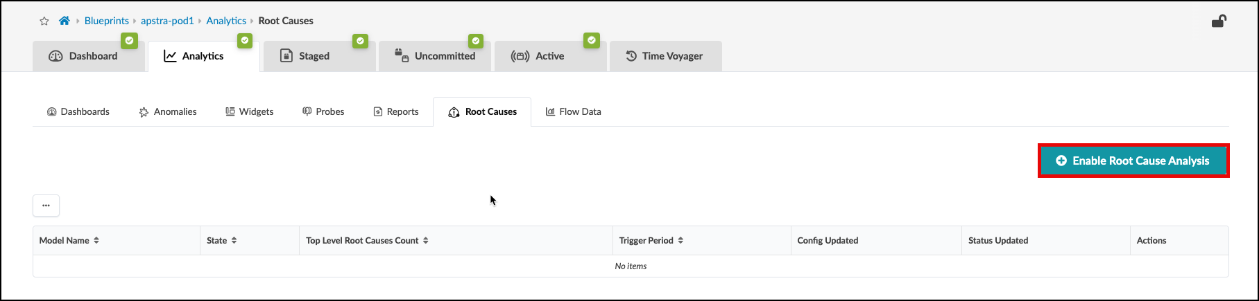
From the blueprint, navigate to Analytics > Root Causes and click Enable Root Cause Analysis. You can set the trigger period to any value, if you wish. This will enable the RCI probe.
-
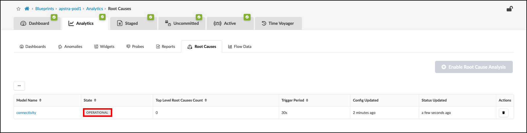
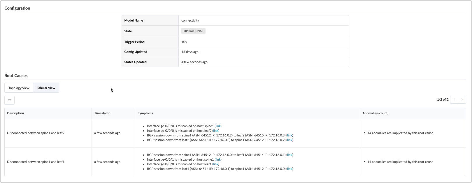
Notice that the connectivity model is now in the operational state.
With Root Cause Identification enabled, link or interface failures will be identified with precision. RCI can be tested in this lab pod by misconfiguring fabric links.
-
Navigate to the Staged > Physical > Links and choose the Edit tool.

-
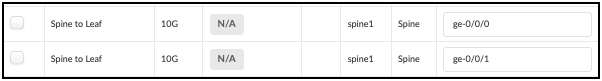
Locate the Spine-to-Leaf links for Spine1 in the table, as shown.
-
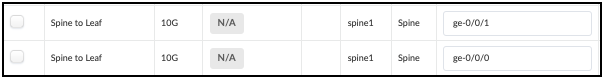
Swap the designated interfaces to the values shown in this table.
-
Navigate to the Uncommitted tab and review the staged changes, then commit them to the Blueprint. Swapping the interface settings will disrupt BGPs peering between fabric devices. This will cause multiple anomaly reports, all of which will be correllated by the Root Cause probe. The view below shows the result of the analysis. Explore all the areas of this view to see the details of the Root Cause diagnosis.
If you wish to return your fabric links to the intended operational state, there are three ways to do this; you can edit the Links table (also known as the Cable Map) again to set the original interface assignments. Or, you could use fetch discovered LLDP data and allow the tool to reset the intended assignment to match the cabling. The last method is Time Voyager, where you could simply restore the fabric snapshot from just before you committed the interface swap.