Lab Guide 1 - Multi-vendor
Multi-tenancy
Virtual Networks
Virtual networks (VNs) are collections of Layer 2 forwarding domains. In an Apstra-managed fabric, a virtual network can be constructed using either VLANs or VXLANs.
Routing Zones are created in a Template where MP-EBGP EVPN is configured as the overlay control protocol. Only inter-rack virtual networks can be associated with Routing Zones. For a virtual network with a Layer 3 SVI, the SVI is associated with a VRF for each Routing Zone, isolating the virtual network SVI from other tenants. This lab uses an MP-EBGP EVPN data center, so we’ll be using VXLAN.
Create Routing Zone
-
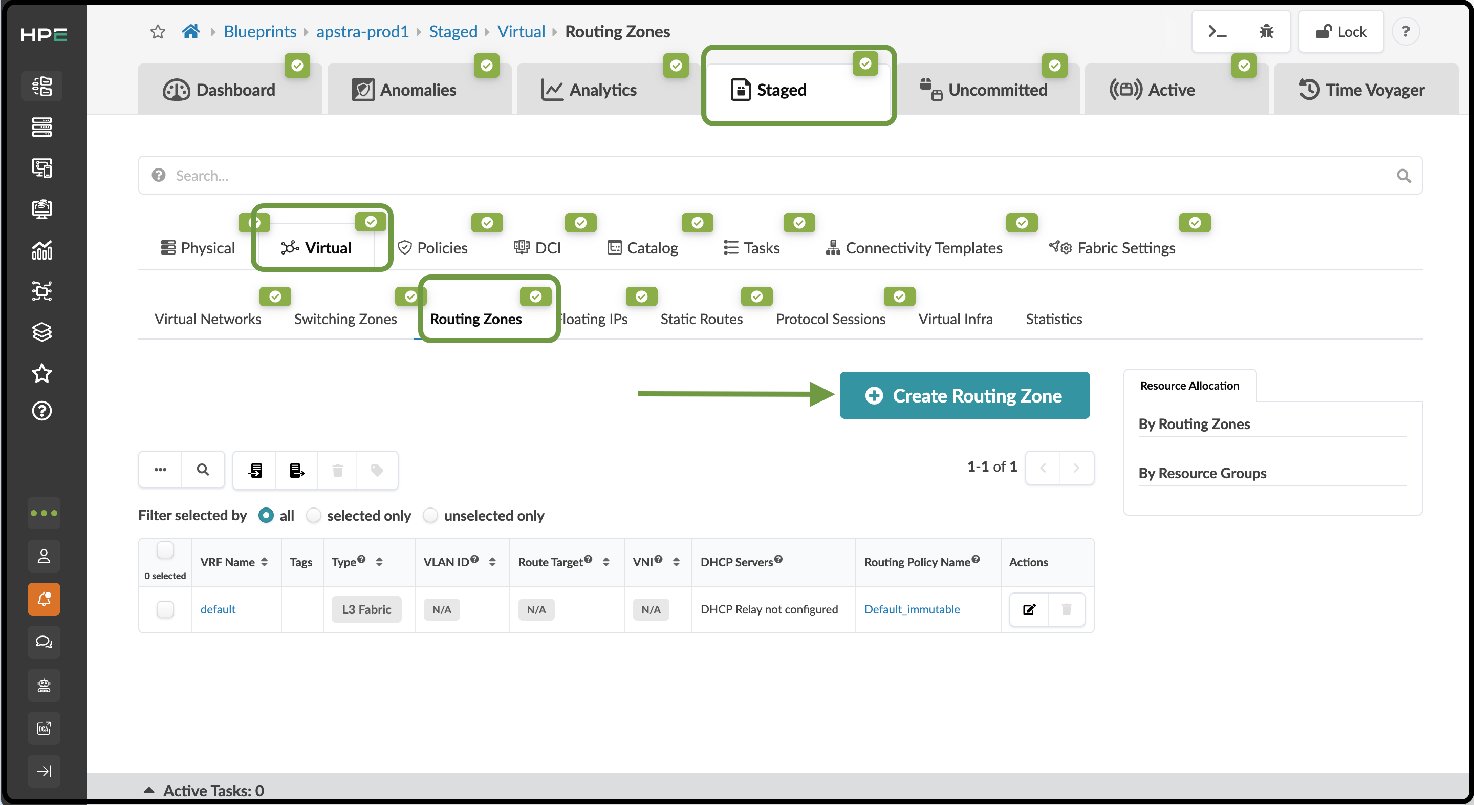
From the Blueprint, navigate to Staged > Virtual > Routing Zones and click Create Routing Zone.
-
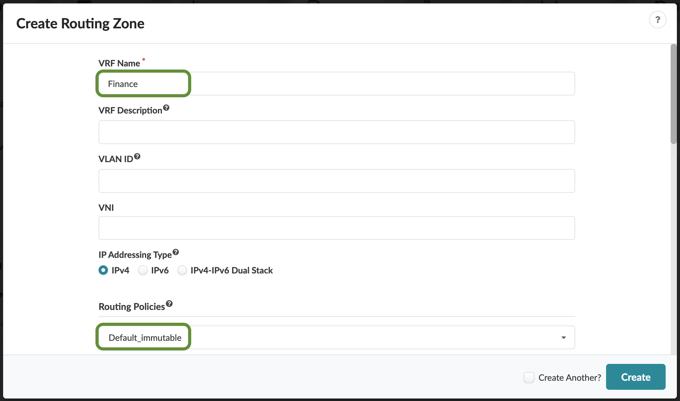
Name the new Routing Zone Finance and select the Default Immutable Routing policy.
-
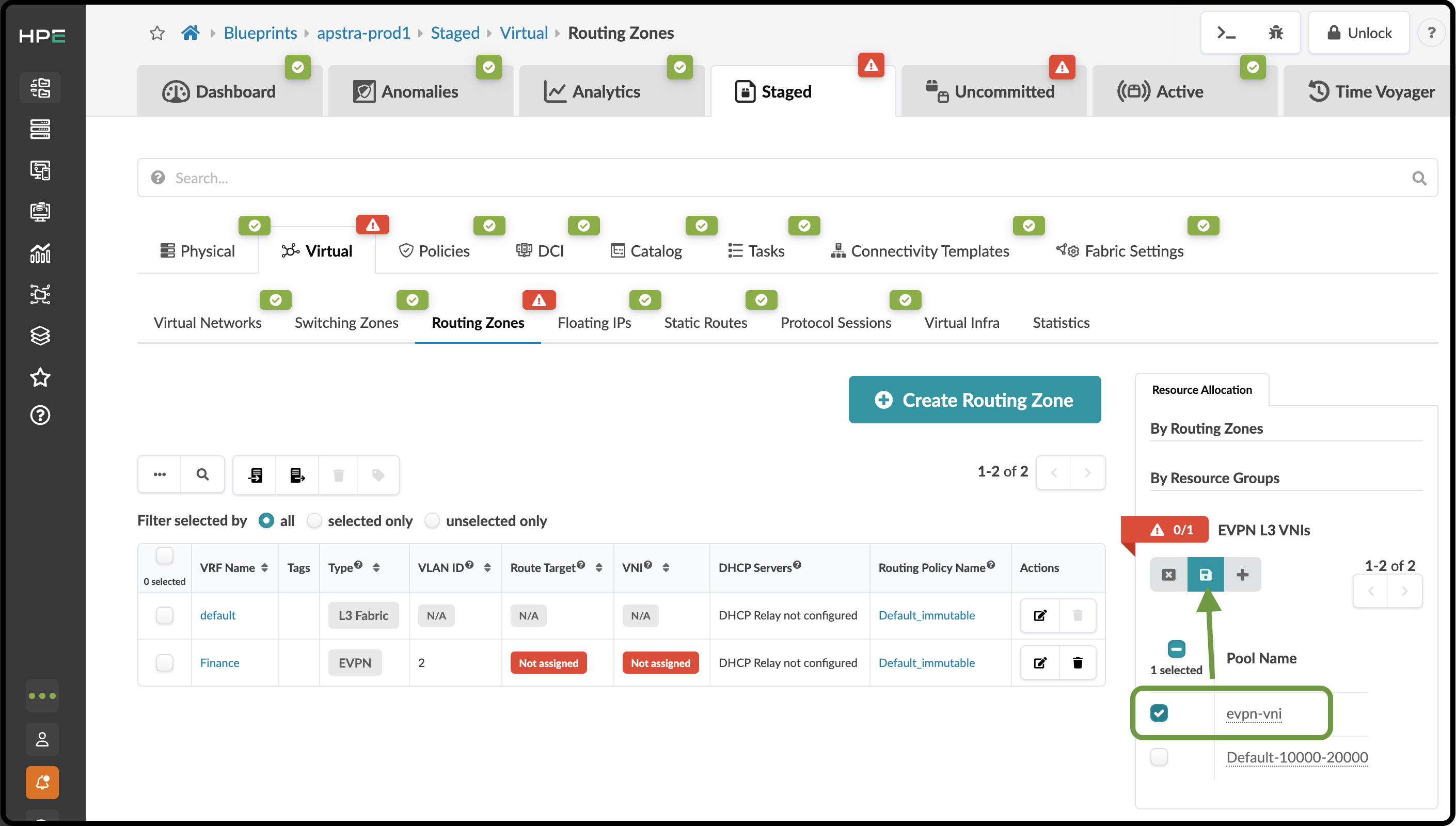
Assign the EVPN L3 VNI pool as shown below.
Table 1. Table Assign Resources to Routing Zone Resource Requirement Resource Pool EVPN L3 VNIs
evpn-vni
-
Click the Save button. The red status indicator turns green when the resource has been successfully assigned.
-
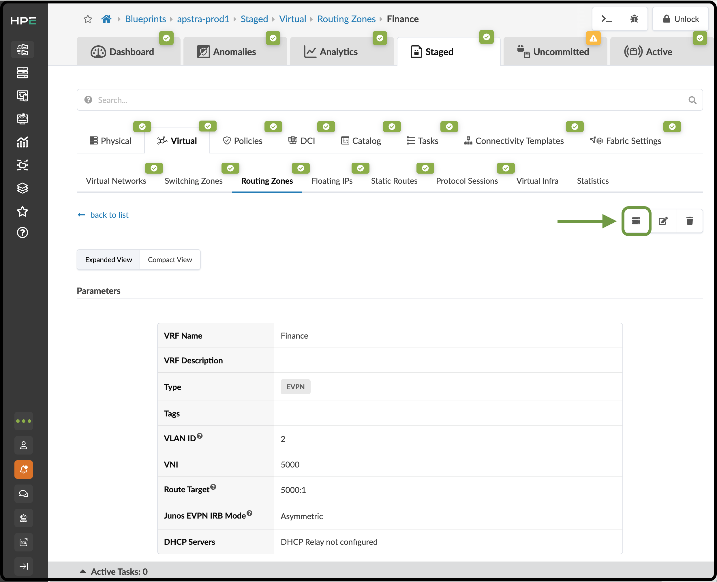
Select the new Finance Routing Zone in the VRF Name column. On the Finance Routing Zone detail page, click the Assign DHCP Servers button.
-
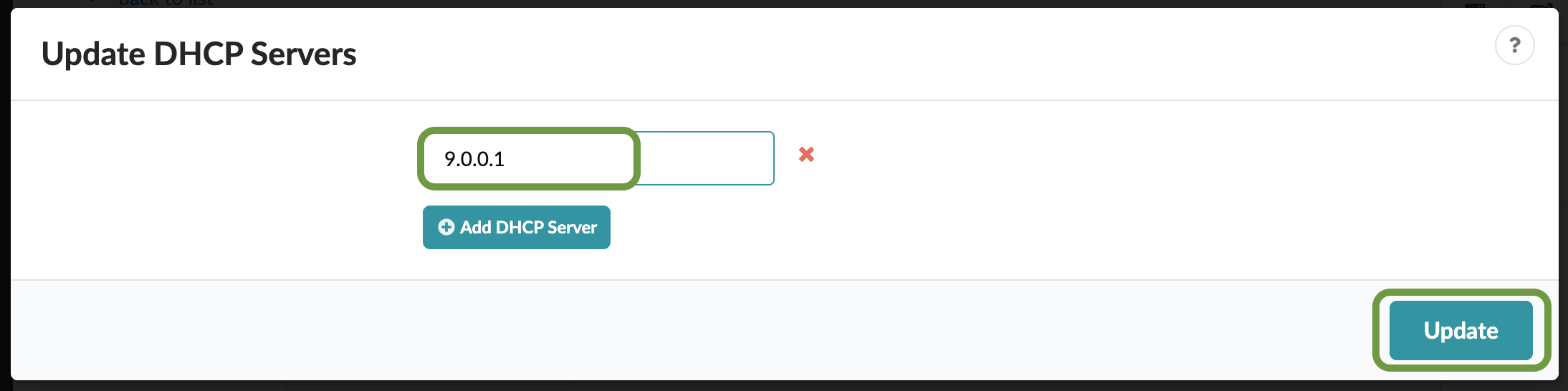
Enter 9.0.0.1 as the DHCP server IP address, then click Update.
-
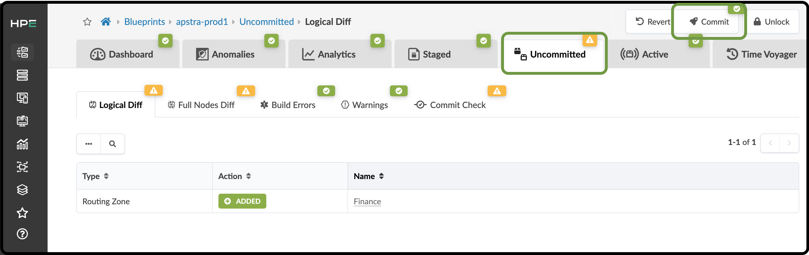
Click Uncommitted to see the staged changes. Take a moment to review this tab and become familiar with how your intent is represented in the staged changes.
-
Click Commit, enter the revision description "Added routing zone", then click Commit to commit the changes to the Active Blueprint.
Update Connectivity Template for New Routing Zone
We now need to update the Connectivity Template created earlier to include the new Routing Zone. This allows the Routing Zone to communicate with networks outside the fabric.
-
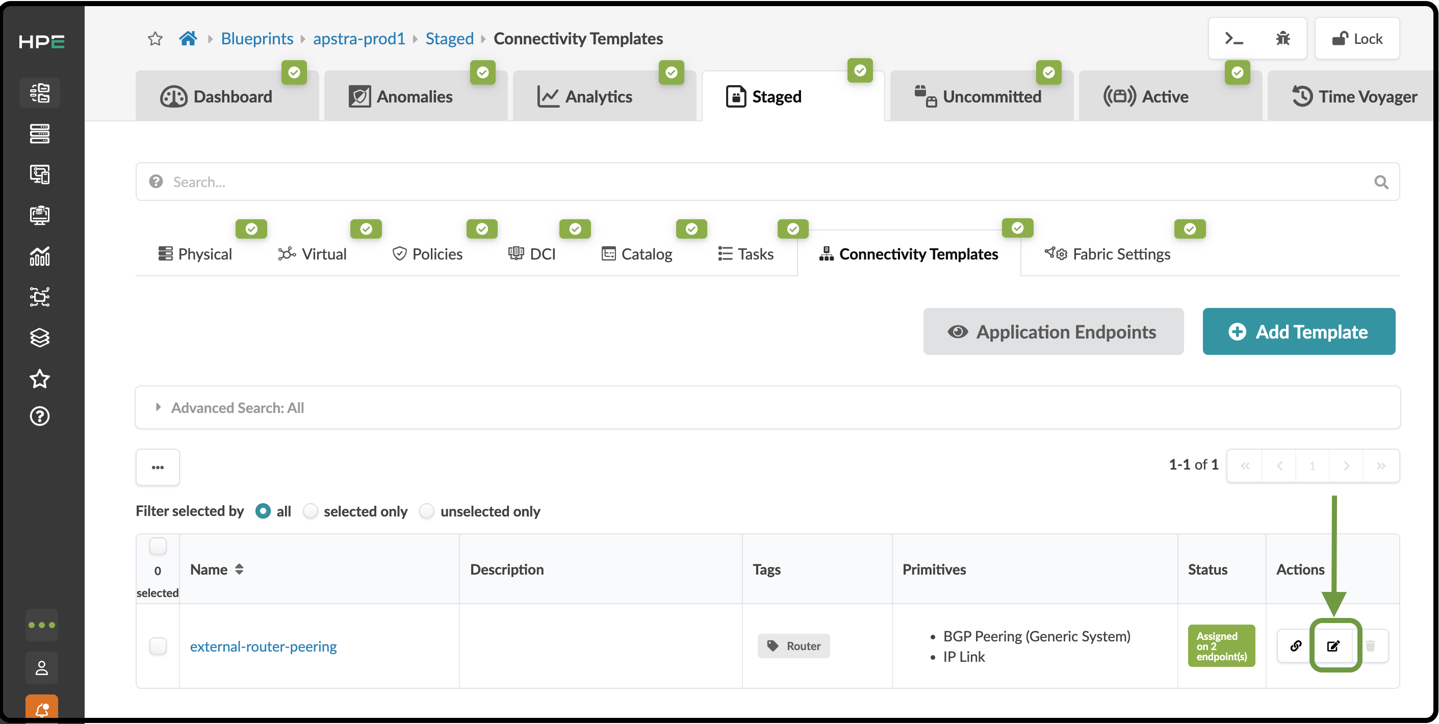
Navigate to Staged > Connectivity Templates and click the Edit button to the right of the external_router_ct that we created earlier.
-
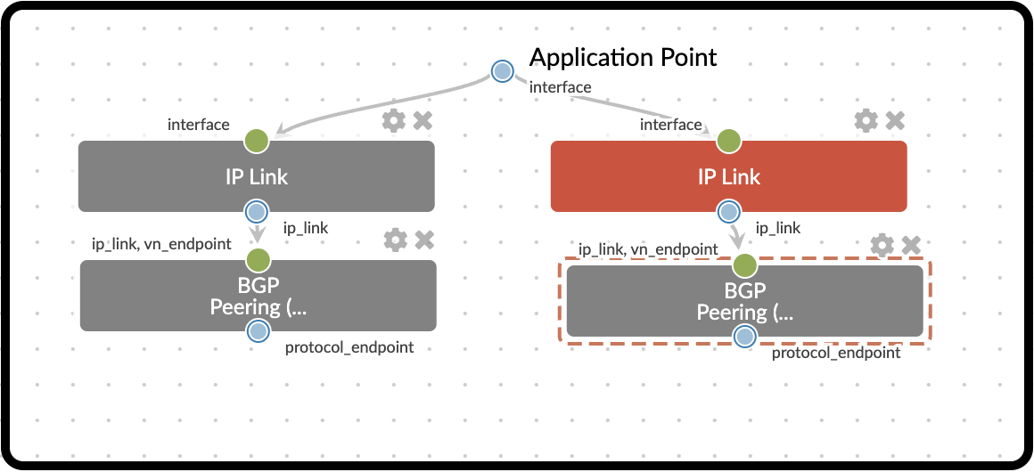
Select the Primitives tab, then click IP Link to add a new primitive to the template. Next, click BGP Peering (Generic System) to add it to the template. You should now see two groups of parameters, each representing VRF peering with the external router.
-
Select the Parameters tab and add the following configuration to the newly added primitives.
Table 2. Table Update Connectivity Template Property Value IP Link (edit title)
ip_link_finance
Interface Type
Tagged
Routing Zone
Finance
VLAN ID
2
BGP Peering (edit title)
bgp_peering_finance
Keep Alive Timer (sec)
30
Hold Time Timer (sec)
90
-
Click Update.
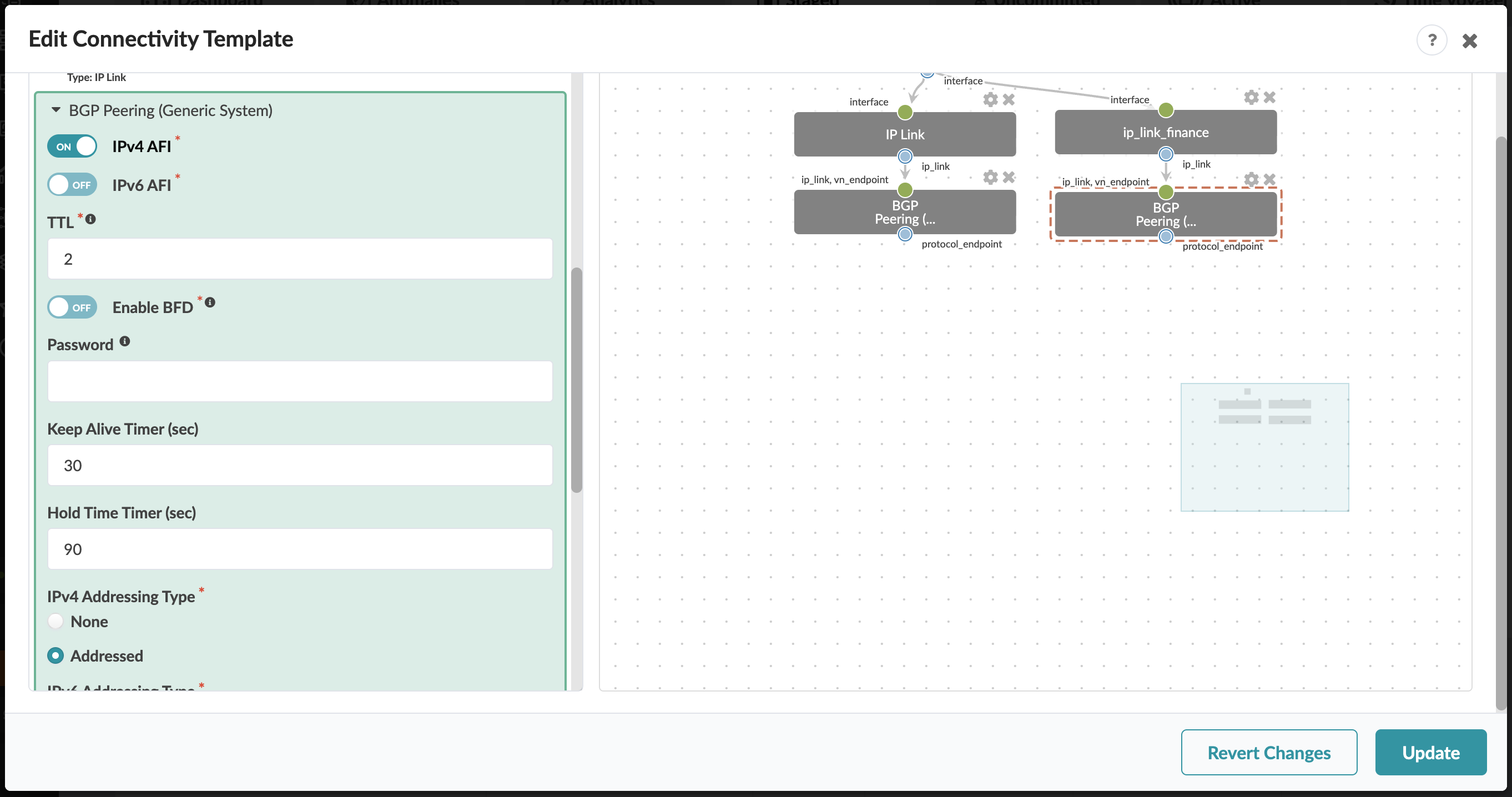
-
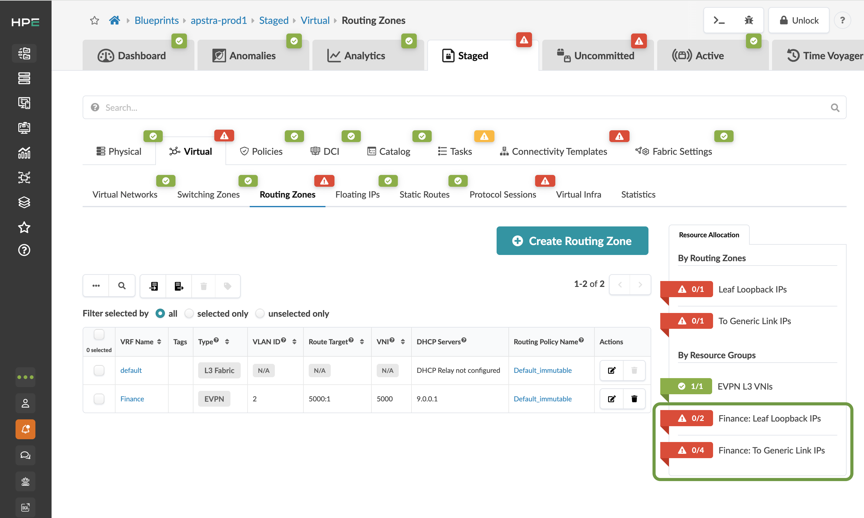
The new IP link added to the Connectivity Template introduces additional resource requirements. Navigate to Staged > Virtual > Routing Zones > Resource Allocation and assign the resources shown in the table below.
Table 3. Table Routing Zone Resource Assignments Property Value Finance: Leaf Loopback IPs
leaf-loopback
Finance: To Generic Link IPs
external-router
Create Virtual Network: finance-www
-
From the Blueprint, navigate to Staged > Virtual > Virtual Networks and click Create Virtual Network.
-
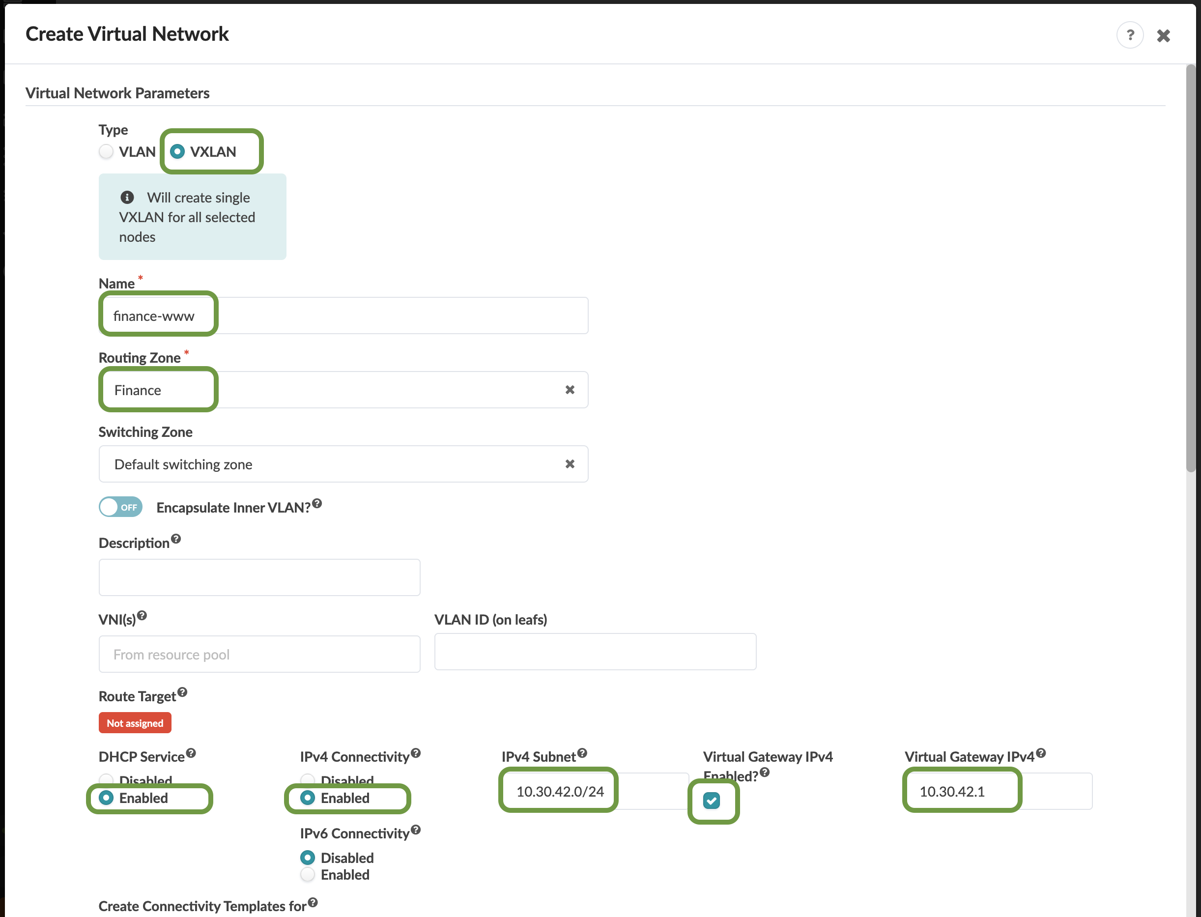
Enter or select the values shown in the table below.
Table 4. Table finance-www VXLAN Values Parameter Value Type
VXLAN
Name
finance-www
Routing Zone
Finance
VNI(s)
leave blank
DHCP Service
Enabled
IPv4 Connectivity
Enabled
IPv4 Subnet
10.30.42.0/24
Virtual Gateway IP
10.30.42.1
Create Connectivity Template for
Tagged
-
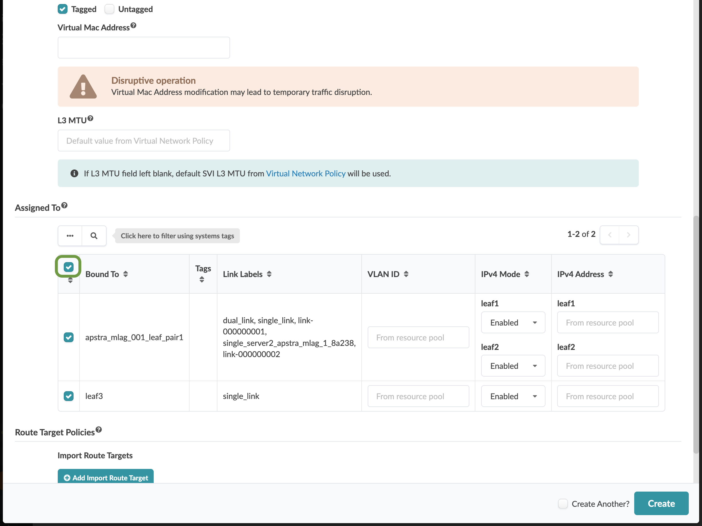
Scroll down to the Assigned To section and select all switches. Leave the VLAN ID fields blank to allow Apstra to automatically assign the VLAN number for each switch.
-
Click Create to create the virtual network and return to the list view. The new finance-www virtual network appears in the list. You will see red indicators showing where resources are needed. We will wait to assign the resource pools until we create two more virtual networks.
Create Virtual Network: finance-app
-
Click Create Virtual Network.
-
Enter or select the values shown in the table below.
Table 5. Table finance-app VXLAN Parameters Parameter Value Type
VXLAN
Name
finance-app
Routing Zone
Finance
VNI ID
leave blank
DHCP Service
Enabled
IPv4 Connectivity
Enabled
IPv4 Subnet
10.30.43.0/24
Virtual Gateway IP
10.30.43.1
Create Connectivity Template for
Tagged
-
Scroll down to the Assigned To section and select all switches. Leave the VLAN ID fields blank to allow Apstra to automatically assign the VLAN number.
-
Click Create to create the virtual network and return to the list view. Check whether any additional resources are needed.
Create Inter-rack VXLAN: finance-db
-
Click Create Virtual Network.
-
Enter or select the values shown in the table below.
Table 6. Table finance-db VXLAN Values Parameter Value Type
VXLAN
Name
finance-db
Routing Zone
Finance
VNI ID
leave blank
DHCP Service
Enabled
IPv4 Connectivity
Enabled
IPv4 Subnet
10.30.44.0/24
Virtual Gateway IP
10.30.44.1
Create Connectivity Template for
Tagged
-
Scroll down to the Assigned To section and select all switches. Leave the VLAN ID fields blank to allow Apstra to automatically assign the VLAN number.
-
Click Create to create the virtual network and return to the list view. The new finance-db virtual network appears in the list.
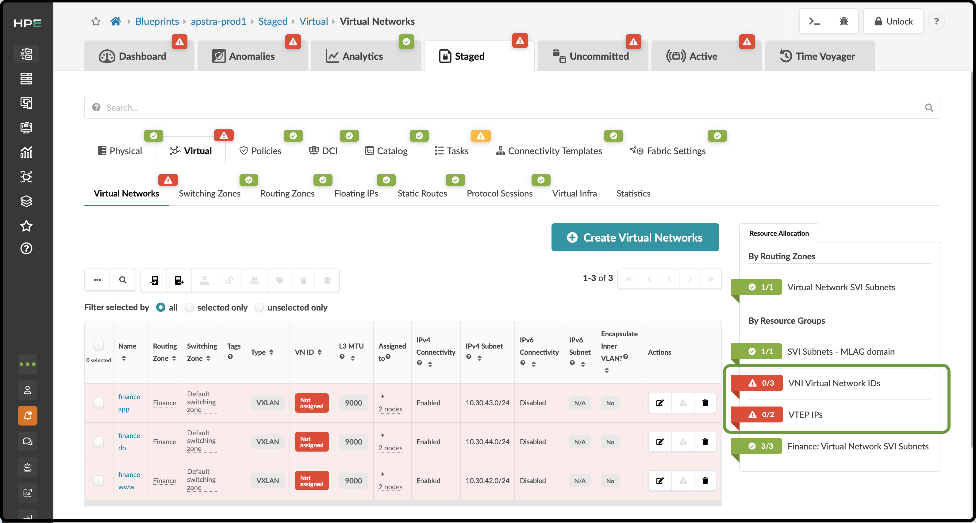
Assign Resources to Virtual Networks
-
Click the red status indicator next to the required resources, then click the Update assignments button to see the available resource pools.
-
Select the pools specified in the table below for the required resource assignments. This will populate the values needed by all three overlays.
Table 7. Table Resources to Virtual Networks Resource Requirement Resource Pool VNI Virtual Network IDs
evpn-vni
VTEP IPs
Private-192.168.0.0/16
-
Click the Save button. When the resources have been successfully assigned, the red status indicators turn green.
Assign Virtual Networks to Server Interfaces
-
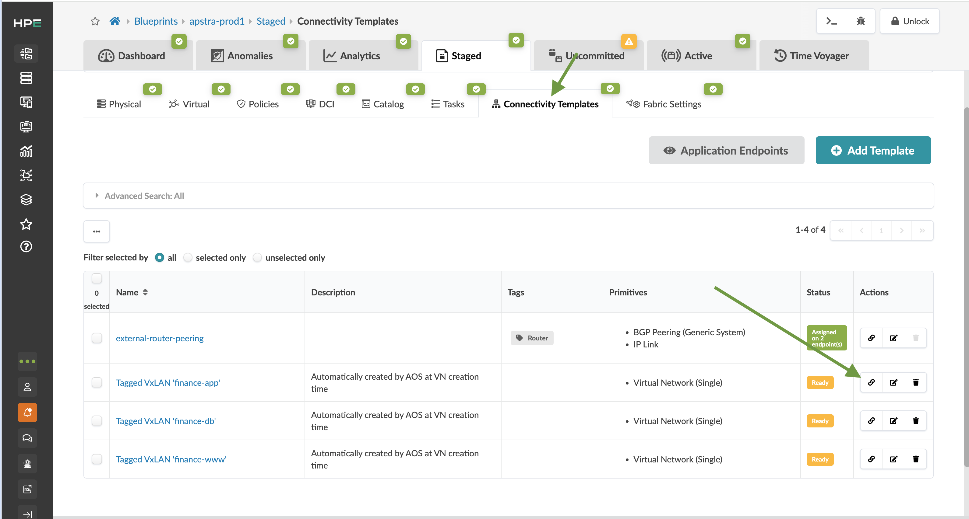
When creating the virtual networks, we chose the option to automatically create a tagged Connectivity Template for each network. Interfaces must now be assigned to these Connectivity Templates. Navigate to Staged > Connectivity Templates. You will see three new Connectivity Templates.
-
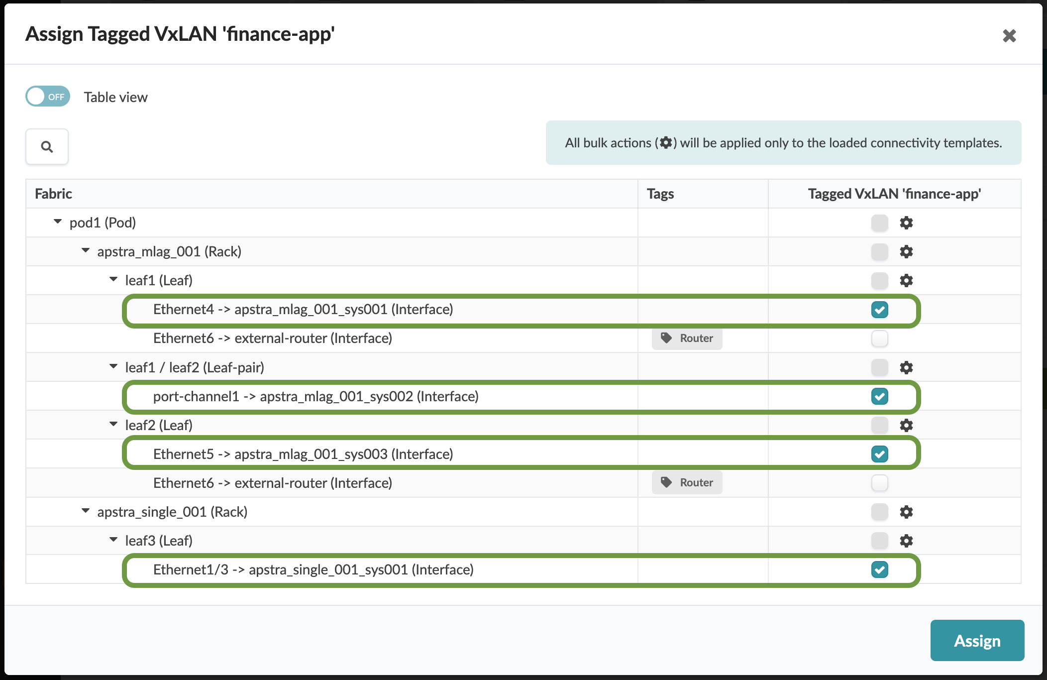
Select the Assign icon for the Tagged VxLAN 'finance-app' Connectivity Template. Select the checkbox to the right of each interface that is not grayed out. Because this Connectivity Template is for server assignments, leave the interfaces tagged with Router unchecked.
-
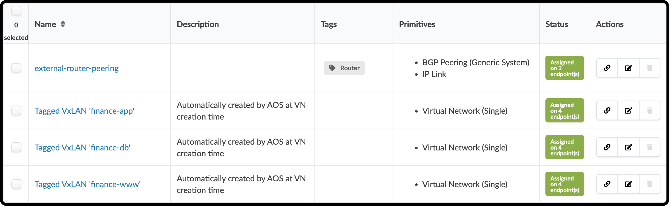
Click the Assign button and repeat these steps for the other two Connectivity Templates. Your assignment table should appear as shown below.
Deploy VXLANs
-
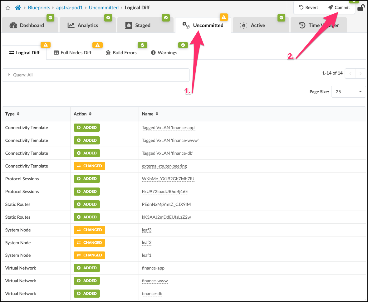
Click Uncommitted to see the new virtual networks listed in the Logical Diff tab.
-
Click Commit, enter the description "Added virtual networks", then click Commit to commit the changes to the Blueprint and deploy the new networks.
-
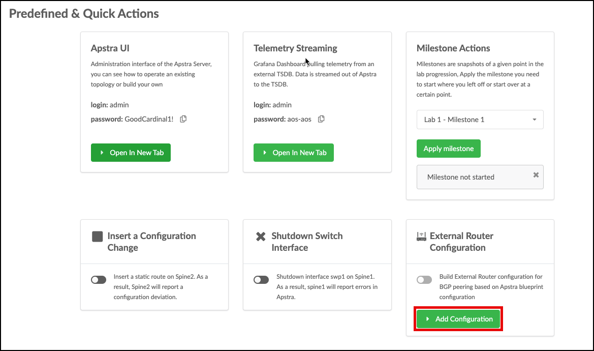
Recall that we previously used the CloudLabs portal to update the external router configuration. We need to perform this step again to apply the peering settings for the new virtual networks.
-
Click Add Configuration and enter apstra-pod1 or yourname-pod1 if the field is not already populated. Click Submit. The new peerings will be configured automatically.
Check Server Connectivity
-
Return to the Apstra CloudLabs portal where you started the topology at the beginning of this lab.
-
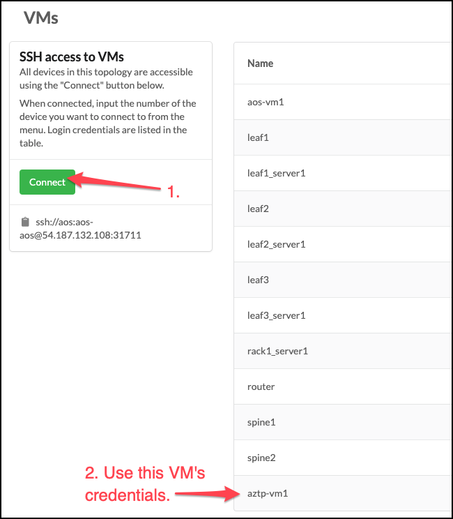
Scroll down to the VMs section, click Connect, and open a terminal. Use the credentials for aztp-vm1 found in the table.
-
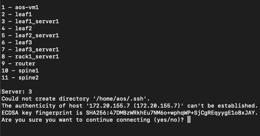
Enter 3 to connect to leaf1_server1. If you are asked whether you want to continue connecting, enter yes.
-
Enter the password for leaf1_server1 (
admin). -
Run
sudo dhclient -r && sudo dhclient. This process takes a moment while the interfaces obtain IP addresses. -
Verify that
eth1.3received an IP address via DHCP by runningip -4 -o addr show eth1.3. -
Repeat the
dhclientprocess for the remaining servers if they have not already obtained an IP address on interfaceeth1.3. -
Ping the other servers to confirm connectivity. For example, to ping leaf2_server1, run
ping 172.20.yoursubnet#.8. Press Ctrl+C to stop the ping.