Lab Guide 1 - Multi-vendor
Rack Type Construction
Rack Types are modular definitions containing top-of-rack switches, workloads, and their associated connections. They also contain redundancy protocol settings and other configuration details. The racks we are about to build will be used in the next stages of modeling our lab fabric. Like the other building blocks we will work with, several predefined examples are included with the server. You can examine them in the list to get a feel for the possibilities. They can be easily cloned and modified to provide the exact characteristics needed to architect a fabric.
In this exercise, however, we are going to create new Rack Types. This demonstrates how easy it is to model our racks. Once created, they can be used repeatedly and modified as needed. The lab example has two Rack Types: one with dual switches and one with a single switch.
This exercise also demonstrates that server workloads can be defined at this stage of construction. Workloads can also be added after the Blueprint is in operation. In fact, servers can be added and removed whenever needed.
Create Single-Homed Rack Type
-
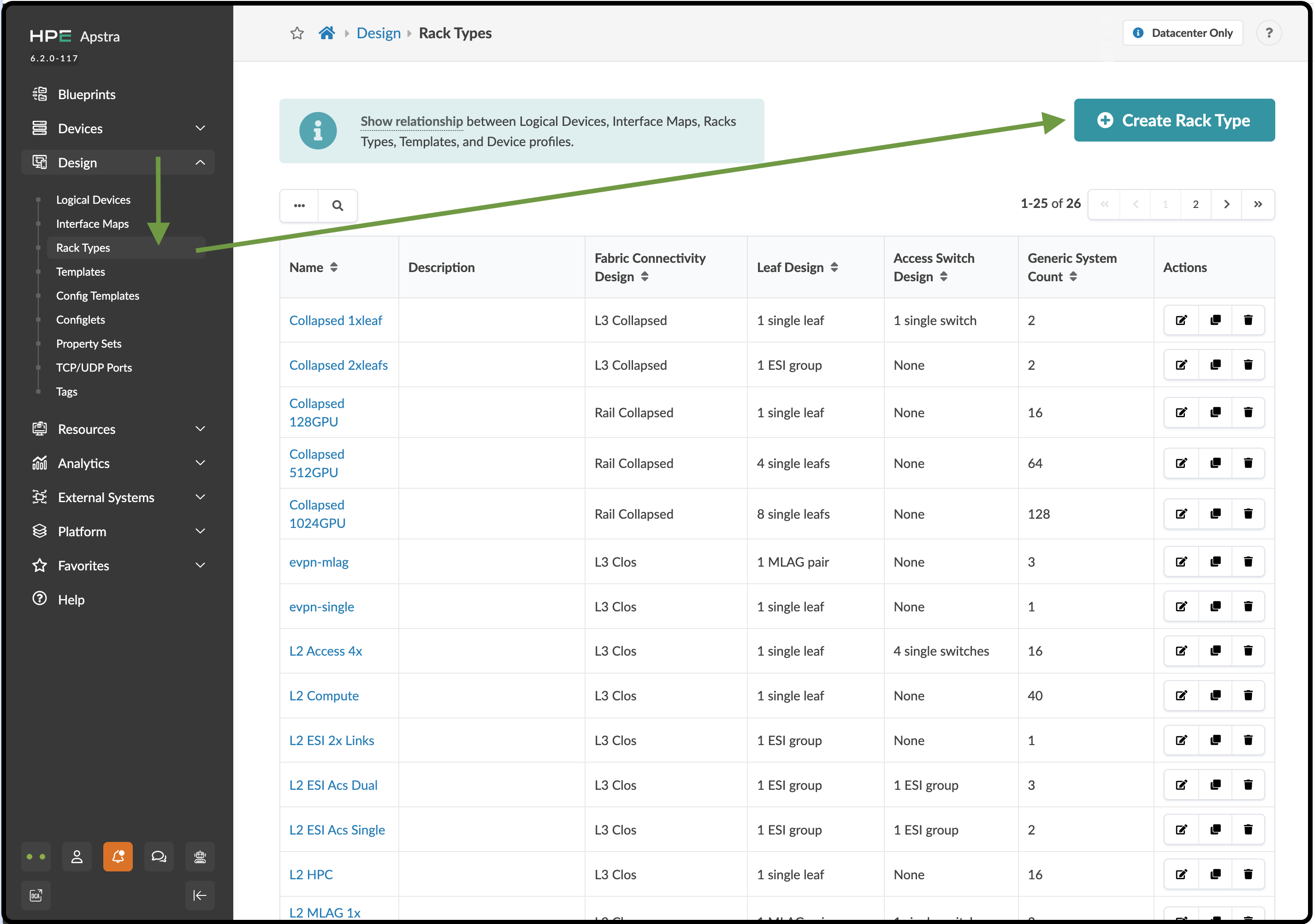
Navigate to Design > Rack Types and click Create in Designer.
-
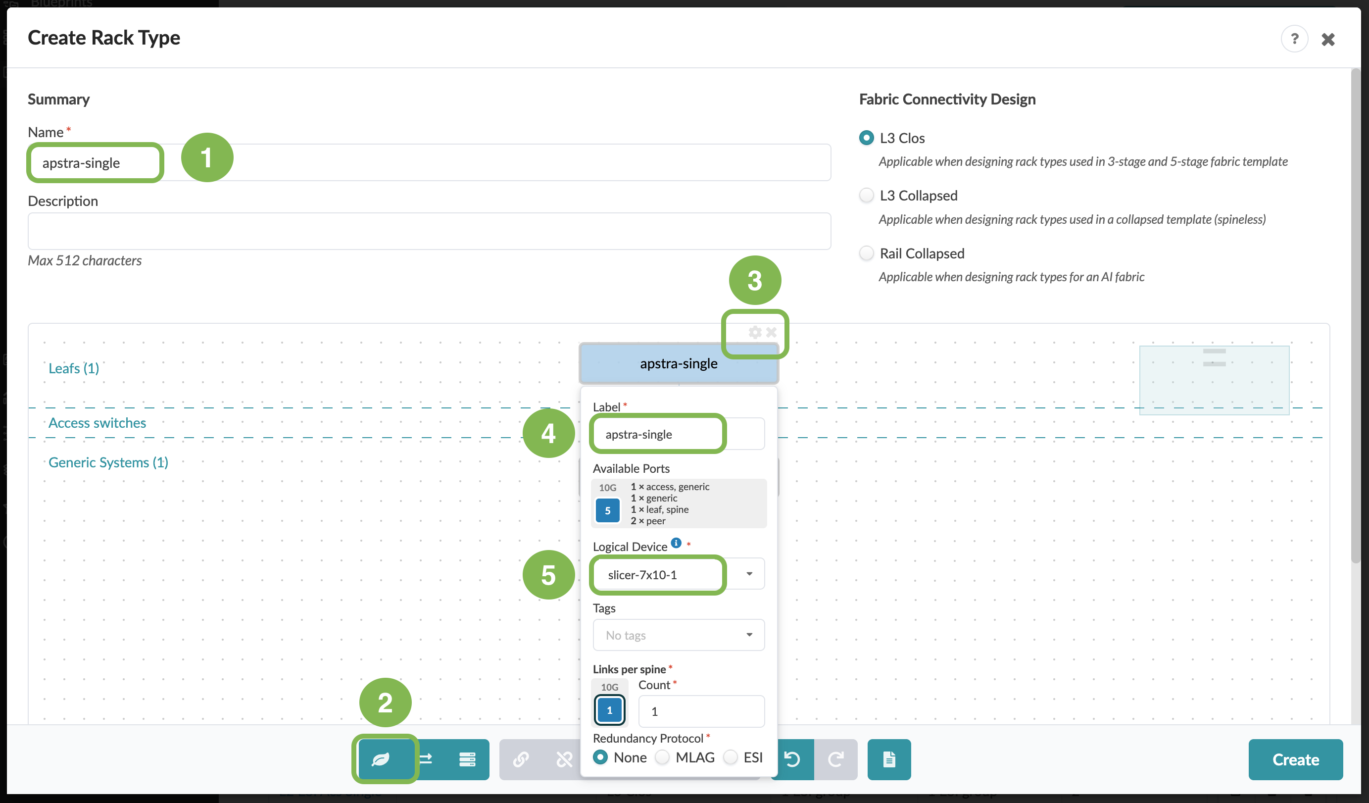
In the Summary section, enter or select the values shown in the table below.
Table 1. Table Single-Homed Rack Type Settings Summary Value Name
apstra-single
Fabric connectivity design
L3 Clos
-
In the menu at the bottom of the view, click the leaf icon to add a single leaf node to this rack. With this node highlighted, select the wrench icon to reveal the node’s properties view. This view can also be opened by clicking the gear icon above the node. Match the settings for this node to the values shown in the table below. Leave the other settings at their default values.
Table 2. Table Single-Homed Rack Type Leaf Values Leaf Value Name
apstra-single
Logical Device
slicer-7x10⁻¹
Links per spine
1
-
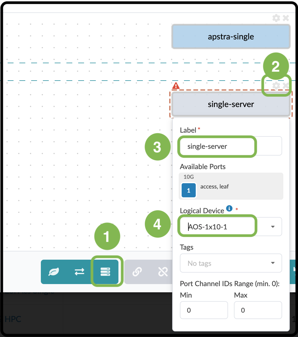
Click the Add Generic icon to add a generic system to the rack. After the Generic System appears, click the wrench icon to reveal the properties view for the selected node. As with the leaf, this view can also be opened by clicking the gear icon above the node. Match the settings shown in the table below. Leave the other settings at their default values.
Table 3. Single-Homed Generic System Values Server Value Name
single-server
Logical Device
AOS-1x10⁻¹
-
Click and drag your mouse to select the switch node and the new generic system. Both will appear inside dashed boxes. You can also use Shift-click on each object to select them. With both selected, click the chain icon to reveal the Link Groups view. Ensure the Count value is 1 and click Create.
Table 4. Generic System Link Values Link Value Label
single-link (or use the default value)
Count
1
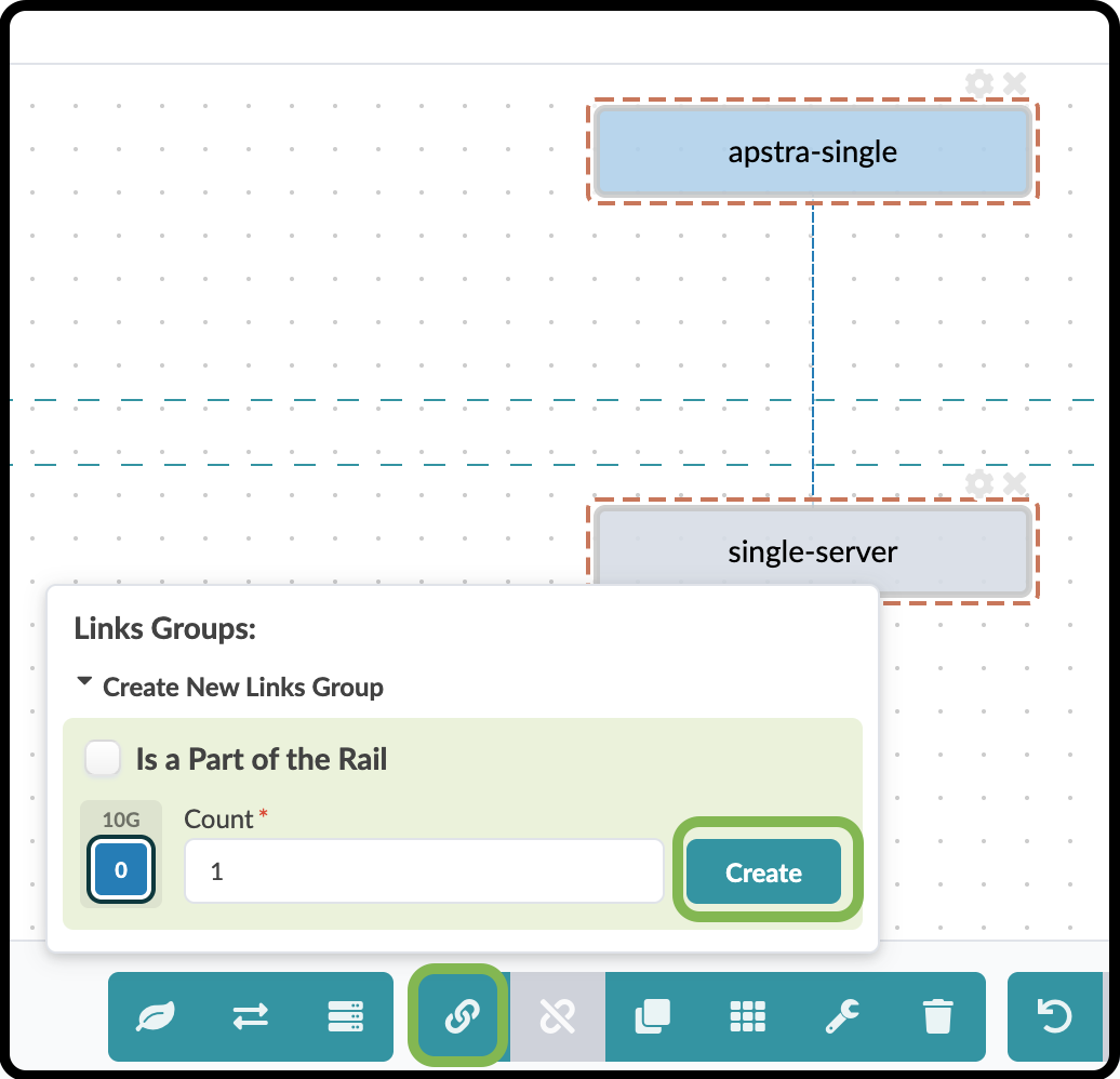
-
A new view appears where you can modify the link label or leave the default value. Do not modify any of the other values. We will use those settings in the next exercise. After you have made the prescribed settings, click Create. The Rack Type will be created, and you will return to the list view.
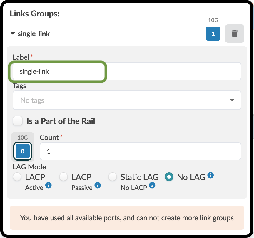
-
To see the details of the rack you just created, click apstra-single in the Rack Type list. It should appear as shown in the image below.
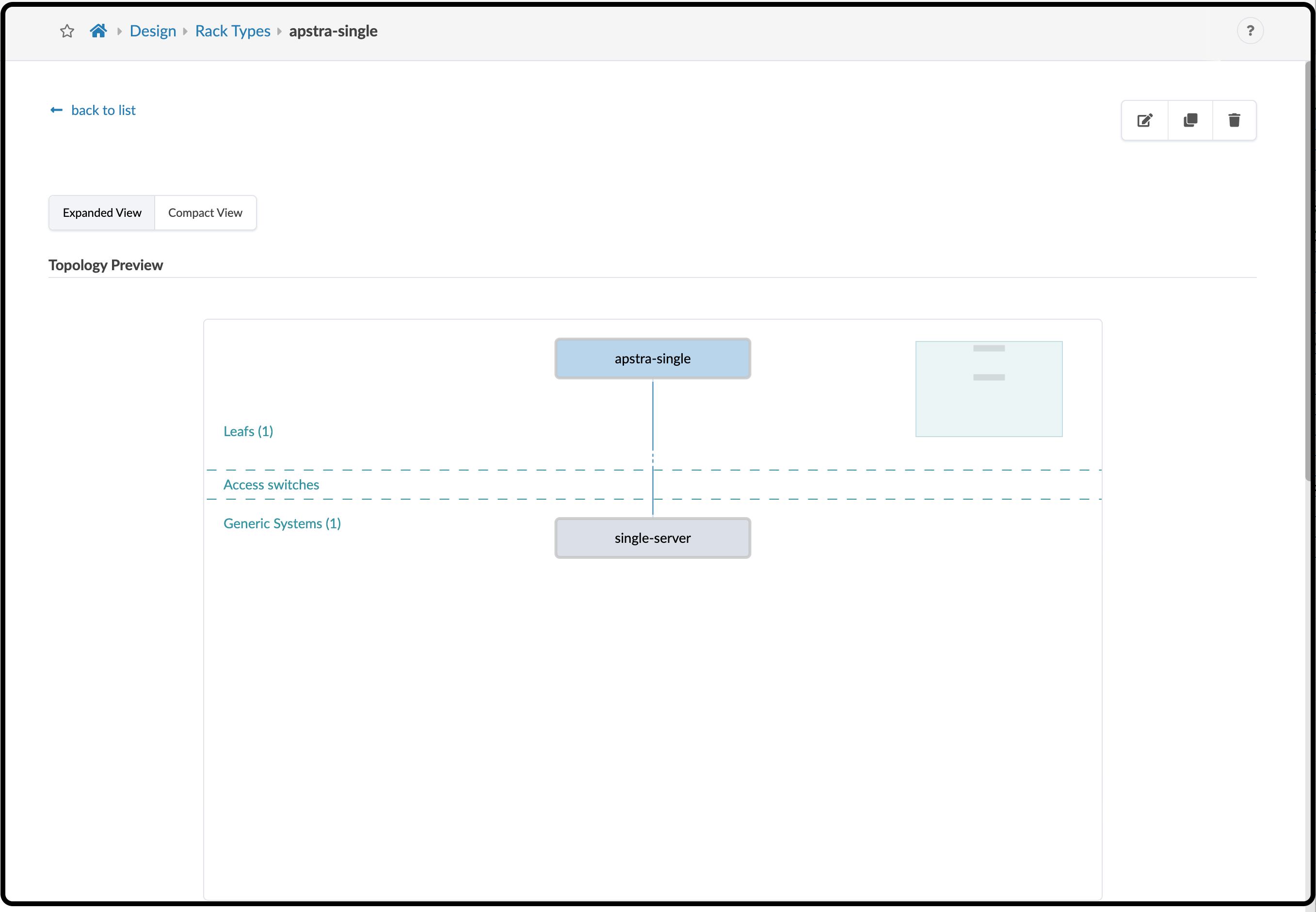
Let’s proceed to the next Rack Type needed for our template.
Create Dual-Homed Rack Type
Data centers frequently provide redundancy for workload devices by using dual top-of-rack switches. Apstra provides flexibility in rack design, so we will configure this rack with redundant leaf switches.
-
From Design > Rack Types, click Create in Designer.
-
In the Summary section, enter or select the values shown in the table below.
Table 5. Dual-Homed Rack Type Summary Values Summary Value Name
apstra-mlag
Fabric connectivity design
L3 Clos
-
In the menu at the bottom of the view, click the leaf icon to add a leaf node to this rack. As before, with this node highlighted, select the wrench icon to reveal the node’s properties view. The gear icon above the node can also be used to open this view. Match the settings for this leaf to the values shown in the table below. This time, set the redundancy protocol to MLAG because this lab uses devices from multiple vendors. Notice that when you do this, a redundant leaf automatically appears in the view. Make sure both switches have all the specified settings.
Table 6. Dual-Homed Rack Type Leaf Values Leaf Value Label
apstra-mlag
Logical Device
slicer-7x10⁻¹
Links per spine
1
Redundancy Protocol
MLAG
MLAG Keepalive VLAN ID
2999 (default setting)
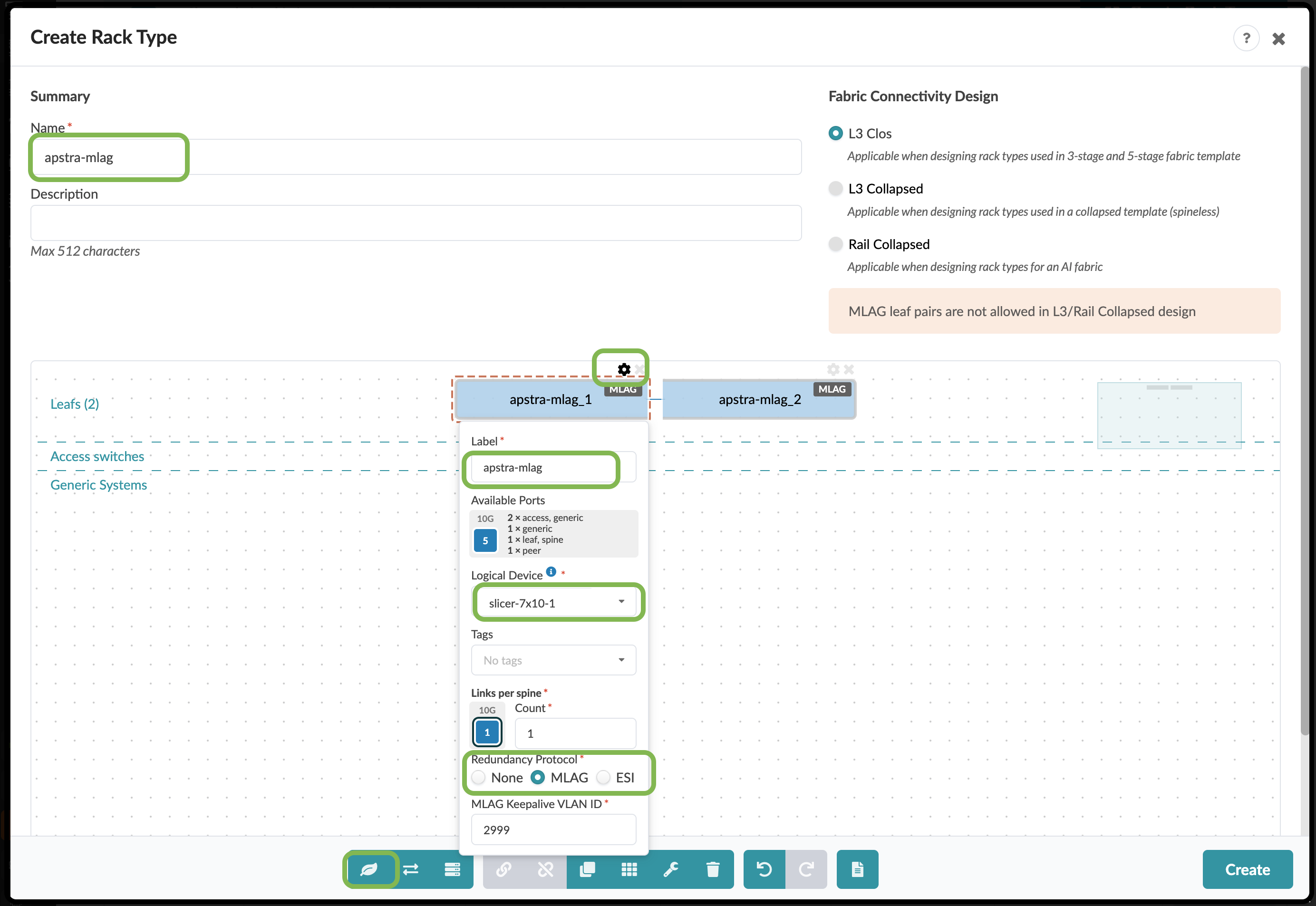
-
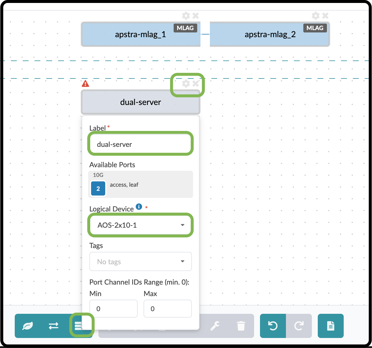
We are going to add three servers and their links to this Rack Type. For the first one, click the Add Generic icon in the menu bar. As before, click the wrench icon to open the properties view. Match the property settings to the values shown in the table below.
Table 7. Dual-Server Values Parameter Value Label
dual-server
Logical Device
AOS-2x10⁻¹
-
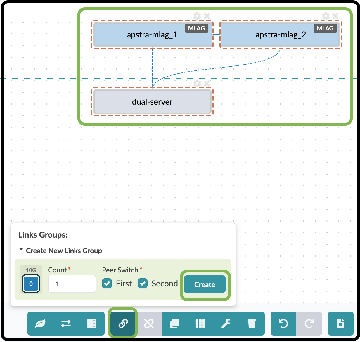
Next, add dual links to this server. Click and drag to select the generic system and both leaf switches. In the view that appears, configure the settings as shown in the table below.
Table 8. Dual-Server Link Group Values 1 Parameter Value Count
1
Peer Switch
First and Second are checked
-
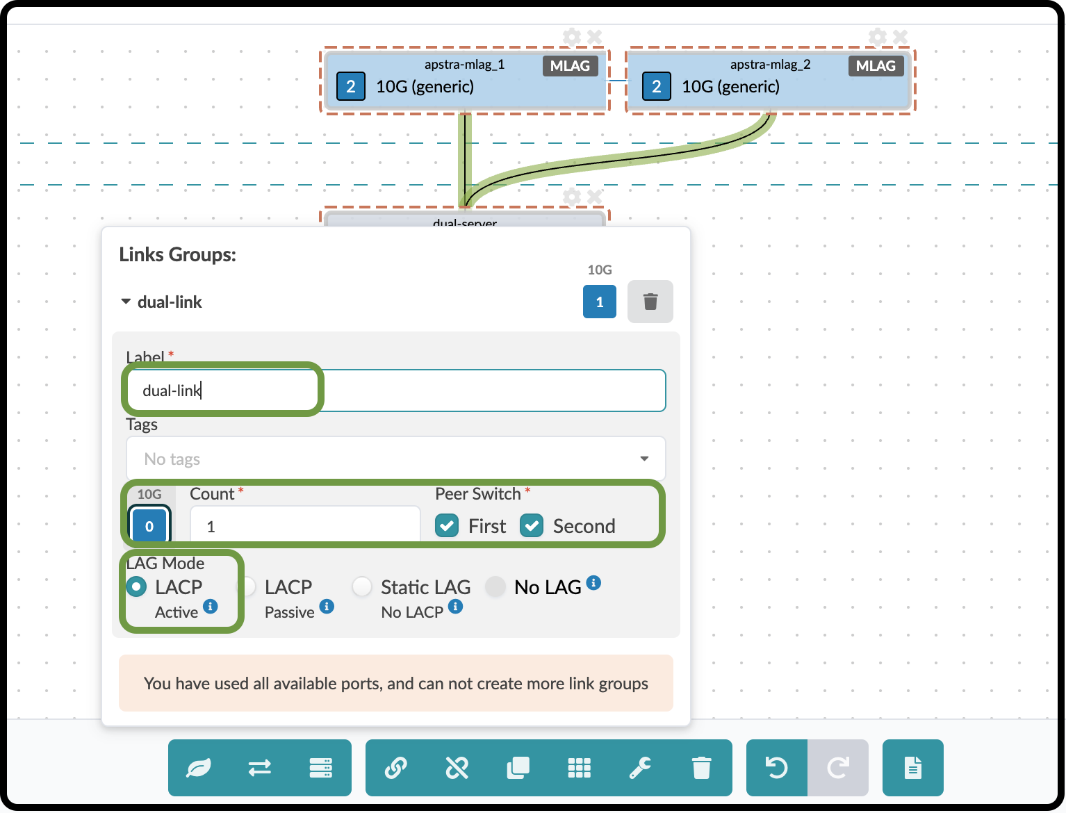
Click Create to open the next view. The peer switch selections appear on both pages.
Table 9. Dual-Server Link Group Values 2 Parameter Value Count
1
Peer Switch
First and Second are checked
LAG Mode
LACP Active
-
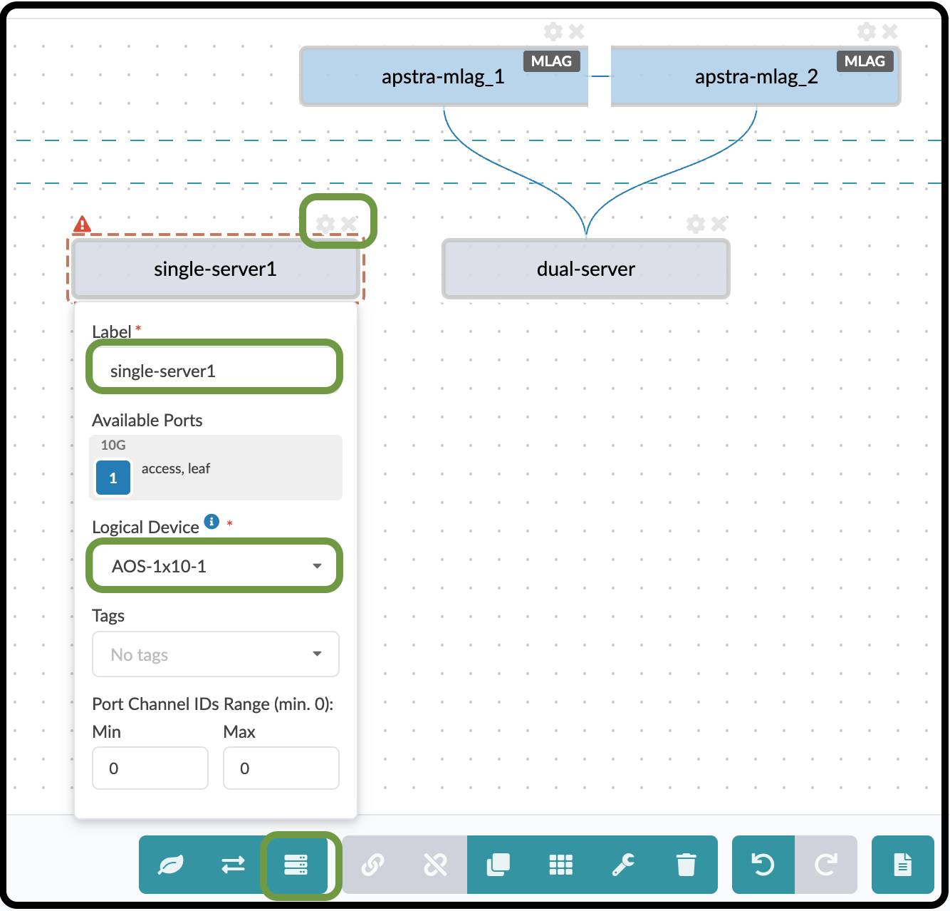
Now, add the first single-connected server to this Rack Type. Click the Add Generic icon.
Table 10. Add Single-Server1 Parameter Value Label
single-server1
Logical Device
AOS-1x10⁻¹
-
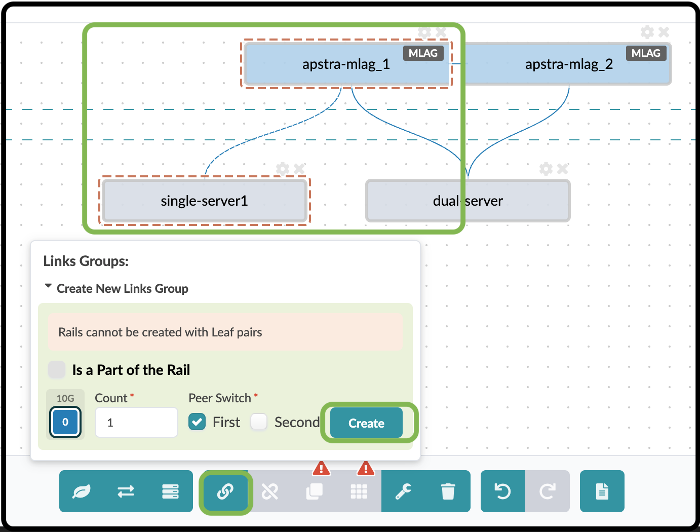
This device requires a single link to switch 1. Click and drag to select the first switch and this server. You may need to move the dual-server slightly to make it easier to select the two devices. The selection box only needs to touch both devices to select them. Match the parameters shown in the table below.
Table 11. Single-Server Link Group Values Parameter Value Count
1
Peer Switch
First
-
Click the Create button for the Link Group, not the Create button on the far right, to open the next view.
-
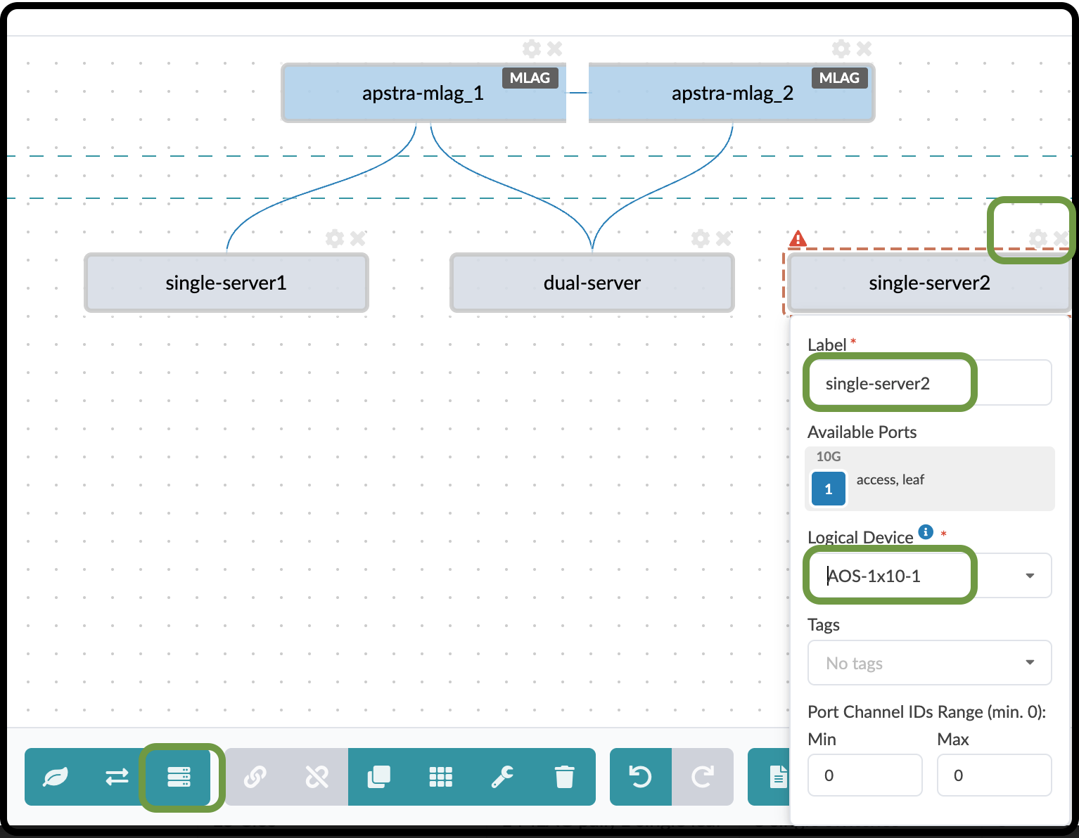
Add another single-connected server to this Rack Type. This one will have a single link connected to switch 2. Click the Add Generic icon. You can drag the new generic system to the right for a cleaner layout.
Table 12. Add Single-Server2 Parameter Value Label
single-server2
Logical Device
AOS-1x10⁻¹
-
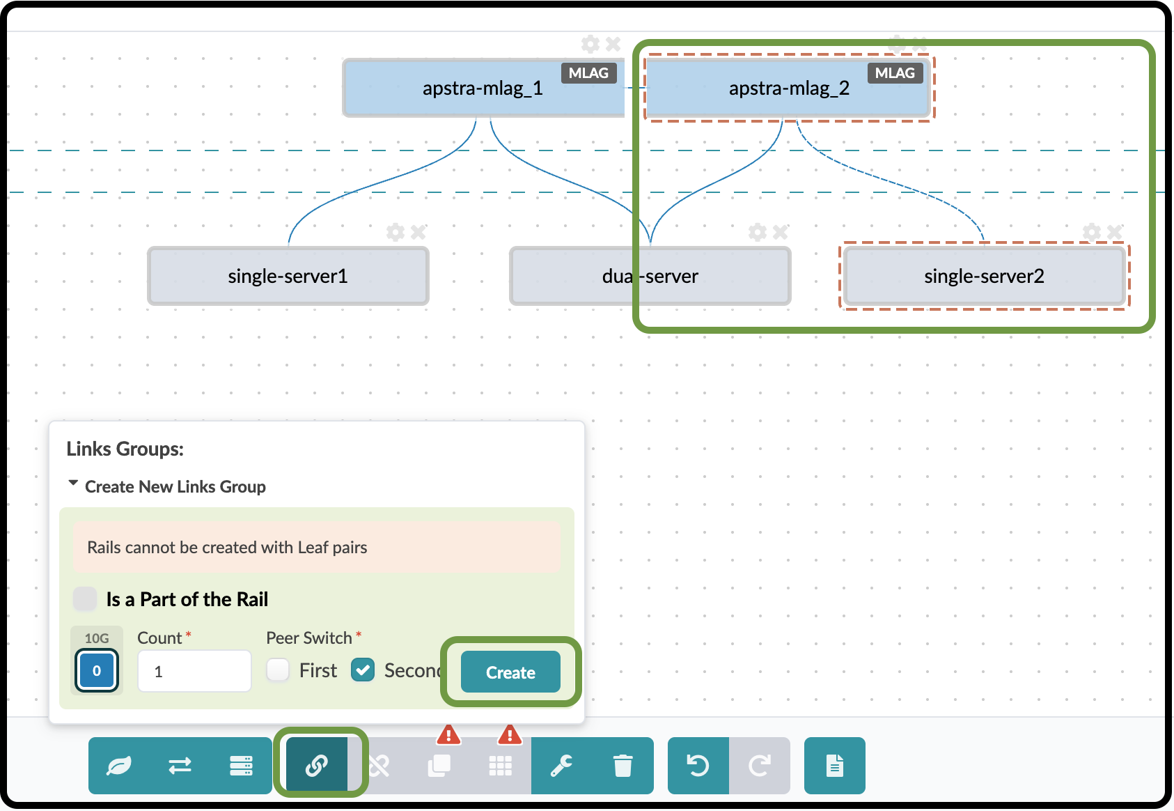
This device requires a single link to switch 2. Click and drag to select the second switch and this server. Click the Link icon and match the parameters shown in the table below.
Table 13. Single-Server2 Link Group Values 1 Parameter Value Count
1
Peer Switch
Second
-
Click the Create button for the Link Group, not the Create button on the far right, to open the next view.
-
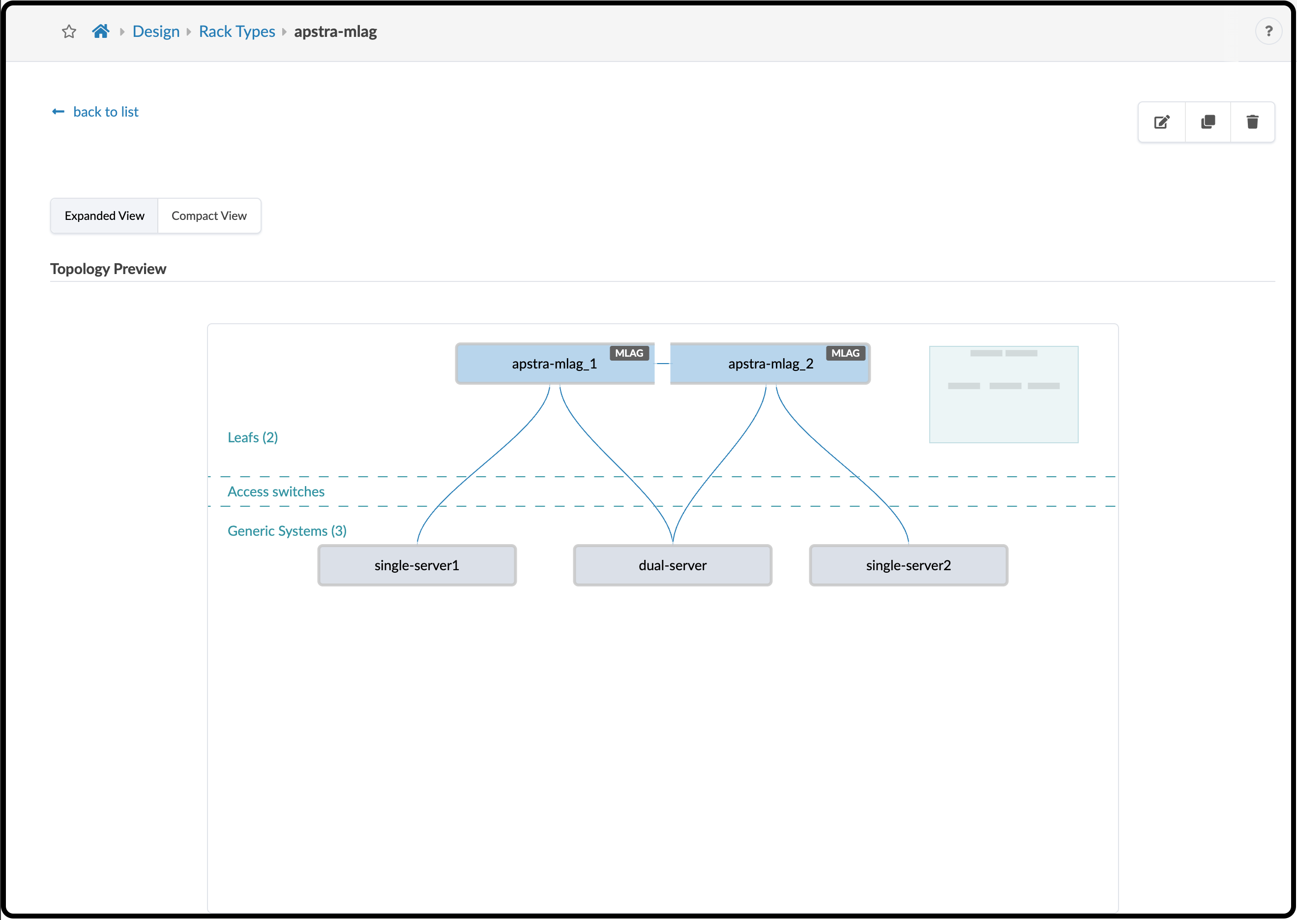
Finally, click the Create button on the lower right to create the Rack Type and return to the Rack Types list. You can see the racks you created at the top of this list. Click apstra-mlag to see the Rack Type you built.