Lab Guide 1 - Multi-vendor
Configure External Router Node
The data center Reference Architecture provides the ability to model external connectivity in a flexible and detailed manner. This exercise walks you through defining an external router that provides connectivity to networks outside the managed fabric. In the remaining exercises, we will also configure this router to provide connectivity between the overlay networks that we build. We define an external generic system to represent the router and its architectural details, including its links, IP addressing, and BGP peering into the fabric’s default VRF.
Add External Generic
-
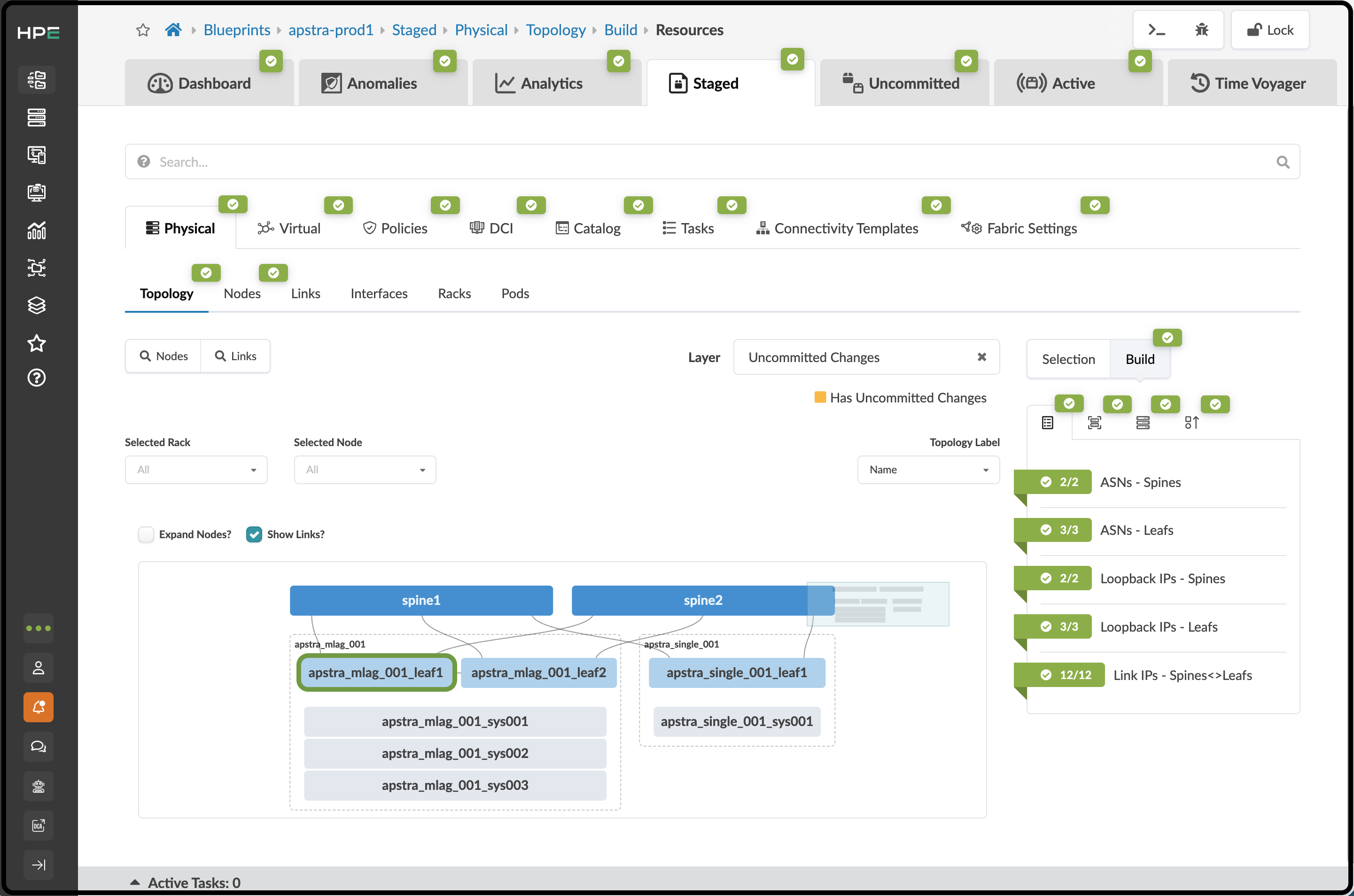
Navigate to Staged > Physical > Topology and select the leftmost device in the apstra_mlag_001 rack. You will move to a new view of the leaf switch.
-
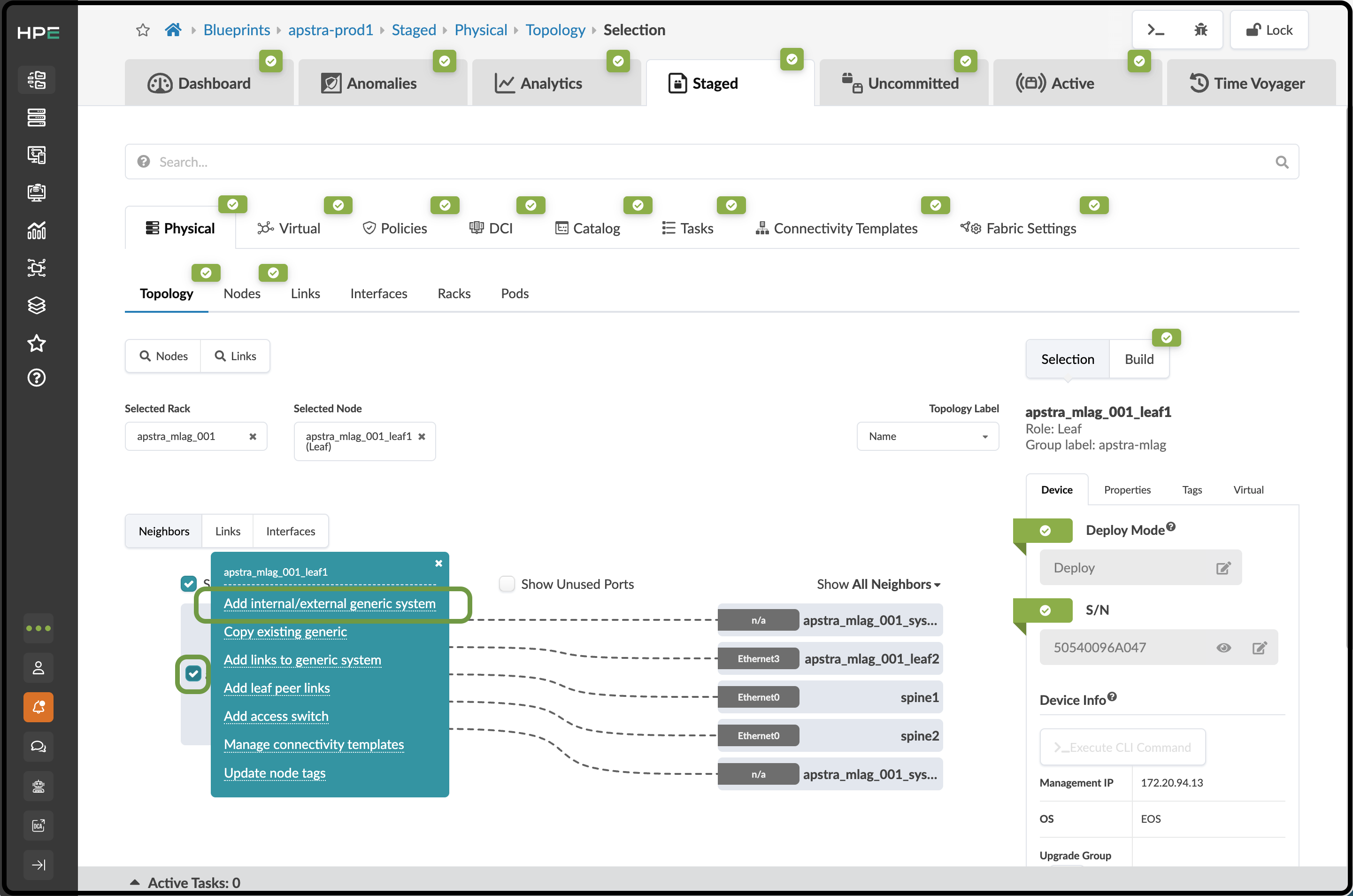
In the MLAG rack, select the left switch and click the box just to the left of the device’s name. When the menu appears, click Add internal/external generic system.
-
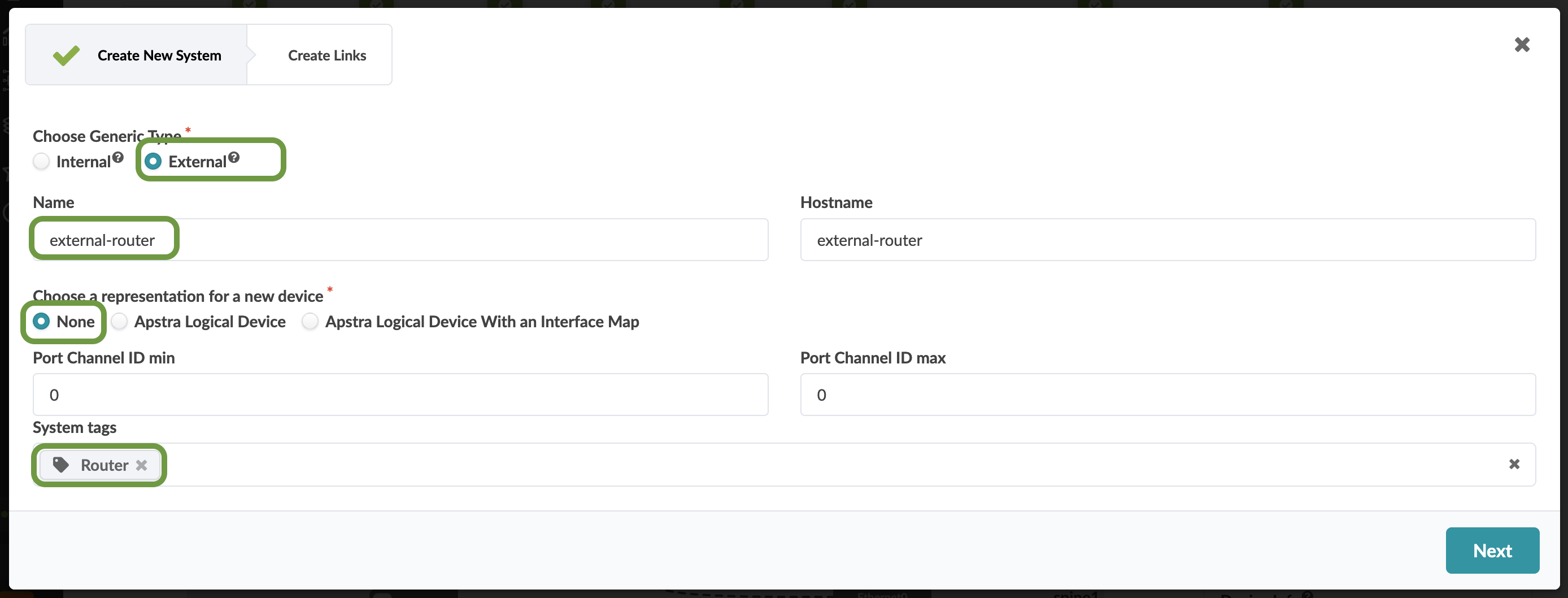
A dialog appears where you can enter the details of the new external device. For Choose Generic Type, select External. Hover over the tooltips to see descriptions of the two types. Enter external-router for the name of this device. The value you enter is automatically entered for the Hostname. The hostname value can be overridden if desired.
-
For Choose a representation for a new device, select None since we don’t need to assign a Logical Device to this device.
-
Next, add a new tag named Router in the System tags field. When you are ready, click Next to move to the Links page.
-
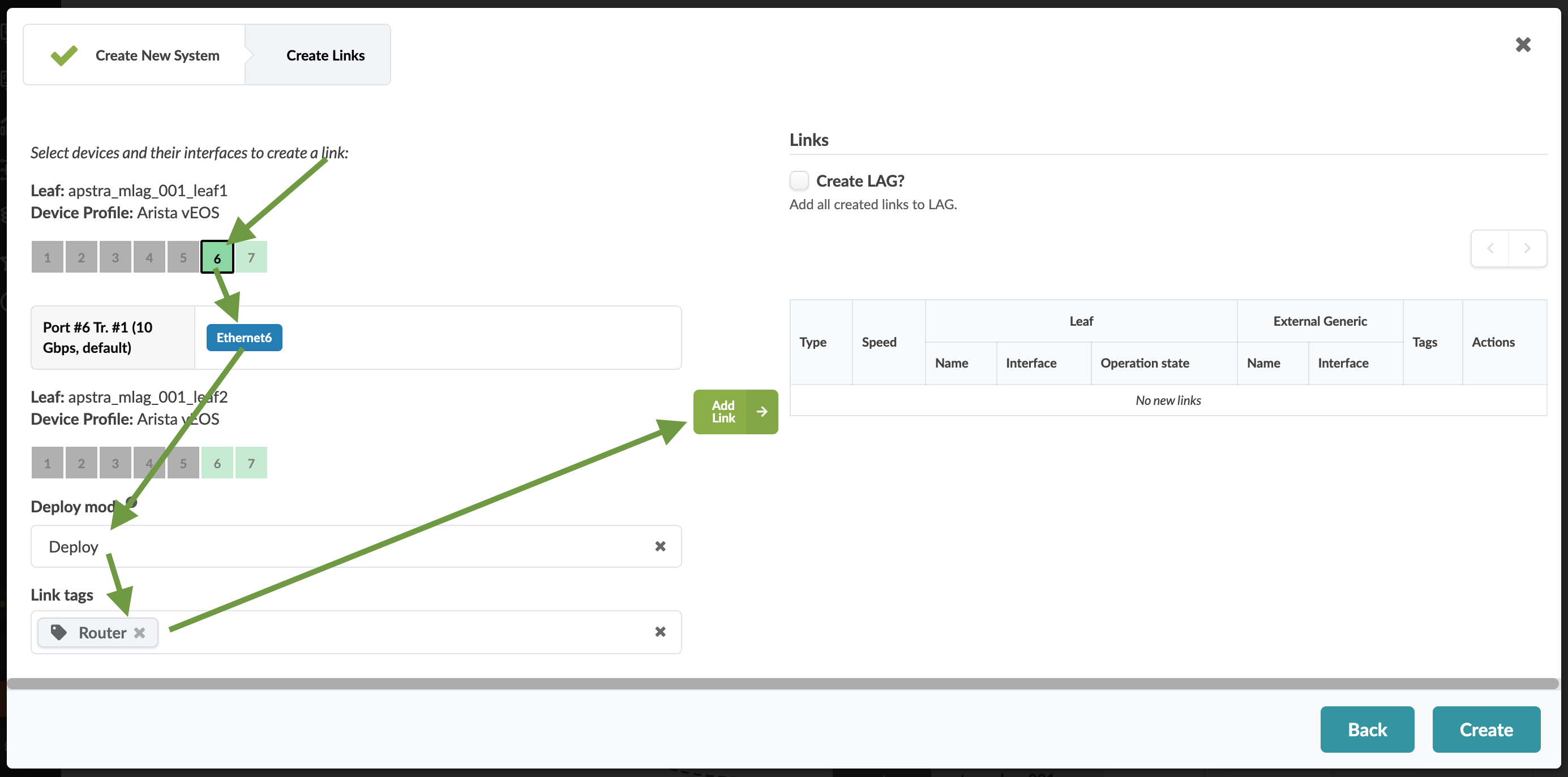
You are presented with a port layout for each switch in the rack. Click to select port 6 on the leaf1 switch and select the 10Gbps transformation. Set Deploy mode to Deploy, then add a tag named Router in the Link Tags section.
-
If everything is correct, the Add Link button in the center of the window turns green. Click it to add the link to the Links list on the right.
-
Repeat the steps above for the second switch. You will end up with the following.
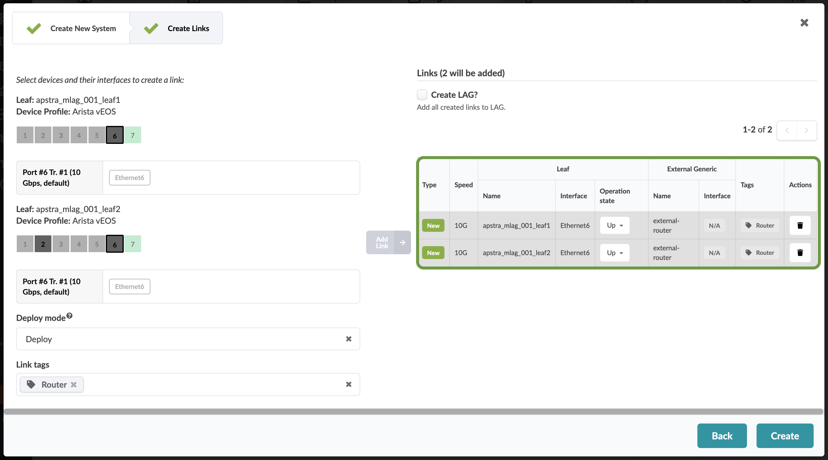
-
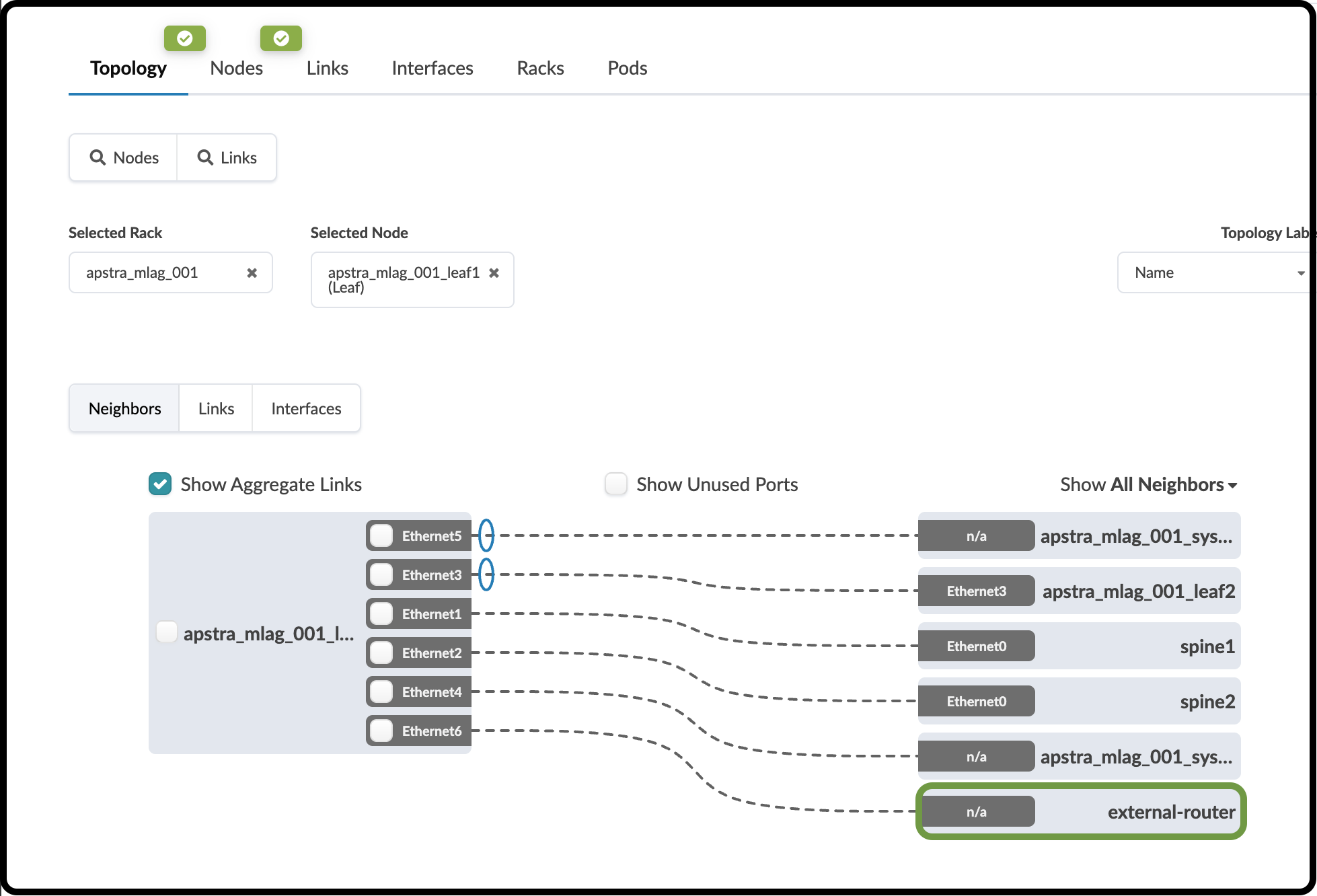
When everything looks correct, click Create to finish creating the external router links. This process stages the addition of the external router and its link details to the Blueprint. You should see this view when the new router object is created. Click the new external-router and you will be taken to another view.
-
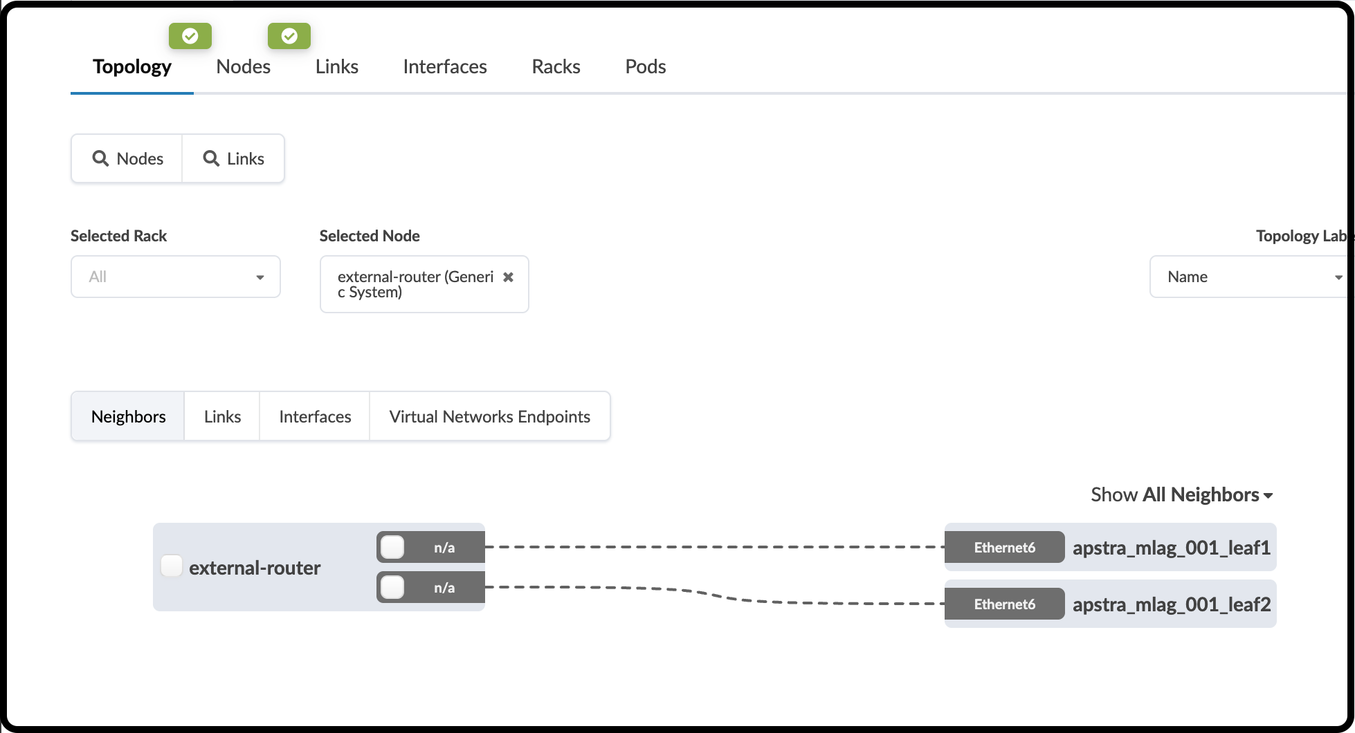
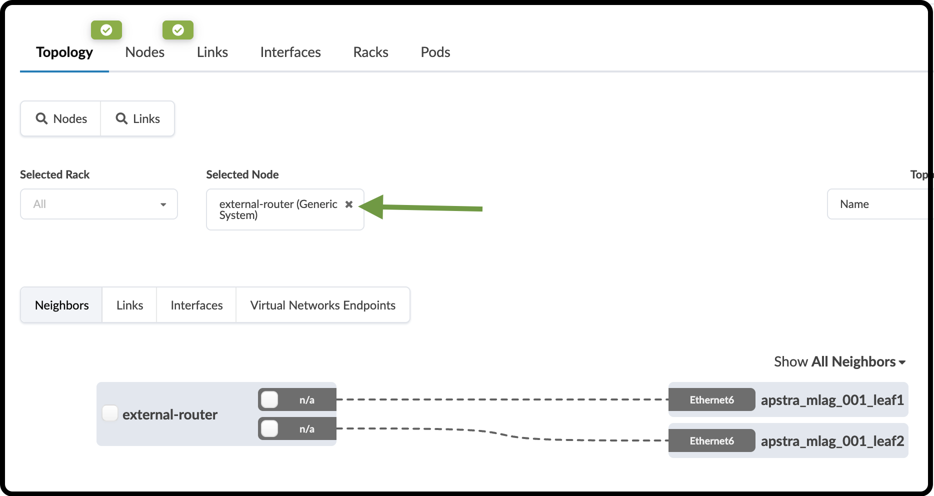
This view shows the new external-router with its links to each of the dual-rack switches.
Configure Default VRF Peering
You have defined how the leaf pair will physically connect to the external router. Next, you need to tell Apstra which Layer 3 characteristics to apply to these links. This information is defined in a Connectivity Template (CT). The CT contains the information needed to create IP links and BGP peering between the leaf pair and the external router. In Cloudlabs, an Ubuntu VM running FRR performs the role of the external router. Let’s begin creating the CT.
-
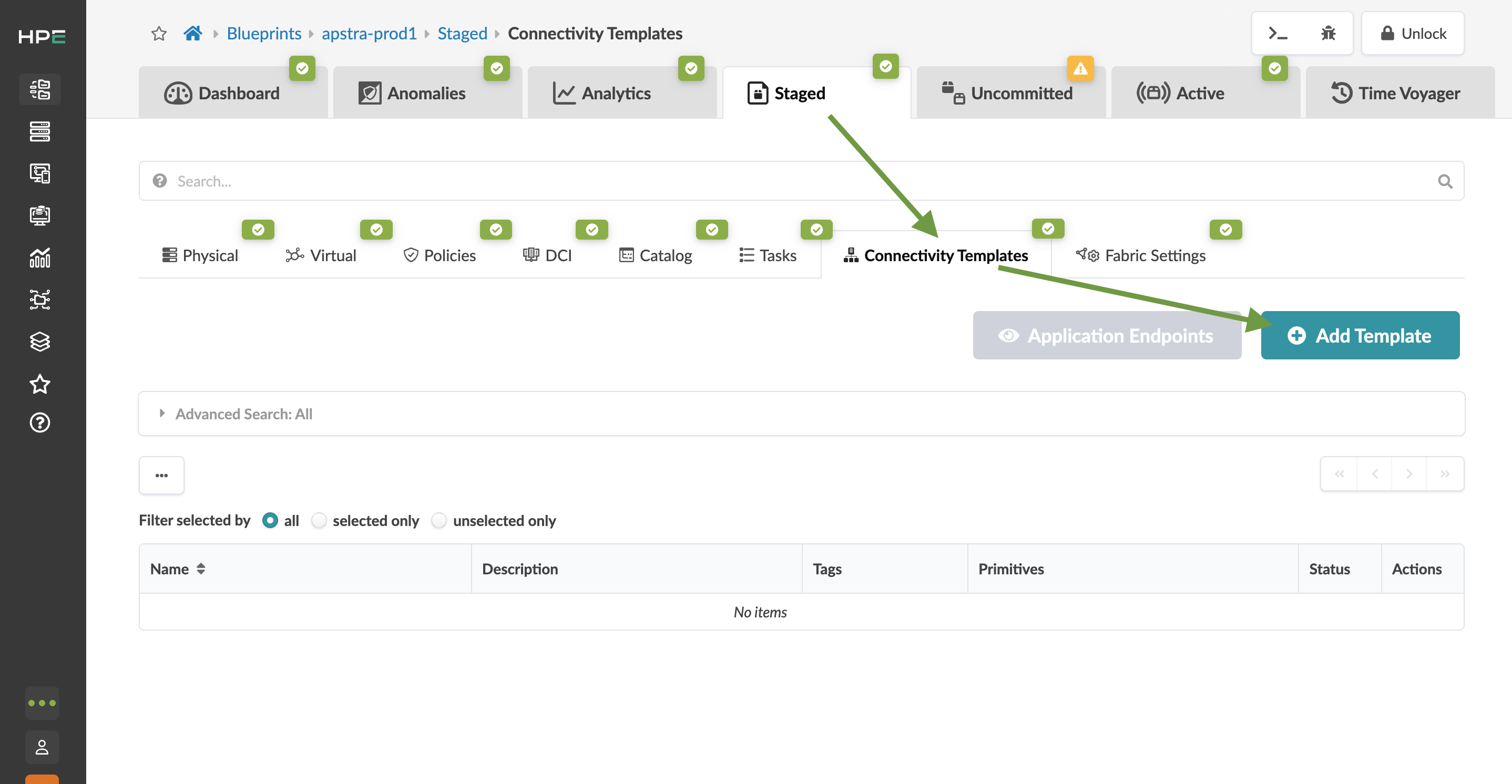
Navigate to Staged > Connectivity Templates and click Add Template.
-
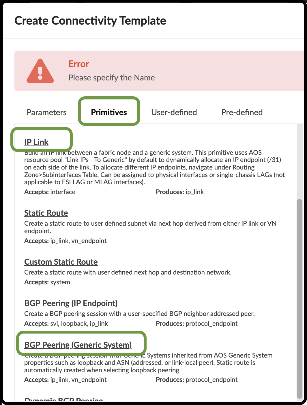
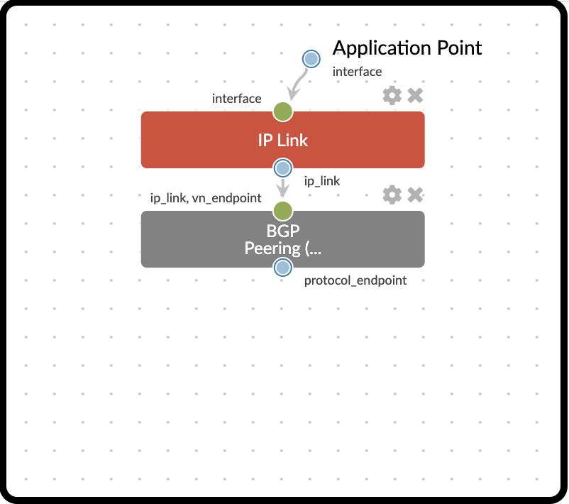
In the dialog that opens, click the Primitives tab, then click IP Link to add the primitive to the template. You will see this object appear in the area to the right of the dialog. Now, click BGP Peering (Generic System) to add it to the IP Link primitive in the template. The object will appear to the right, under the IP Link.
-
This view shows your entries creating the objects in your CT.
-
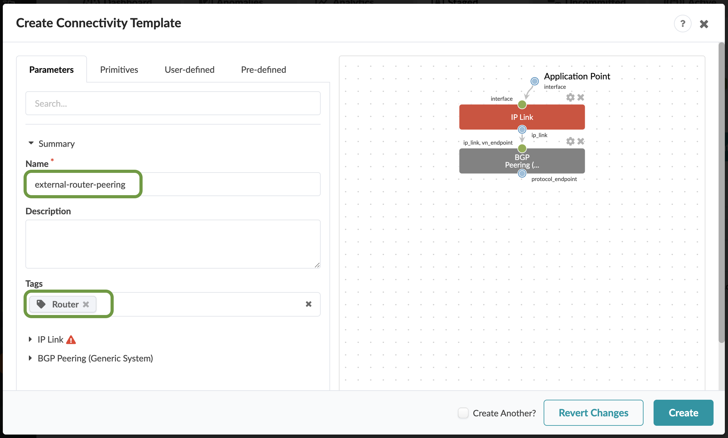
Now, select the Parameters tab to edit the default values.
Table 1. Table Configure Connectivity Template Property Value Title
external-router-peering
Tag
Router
-
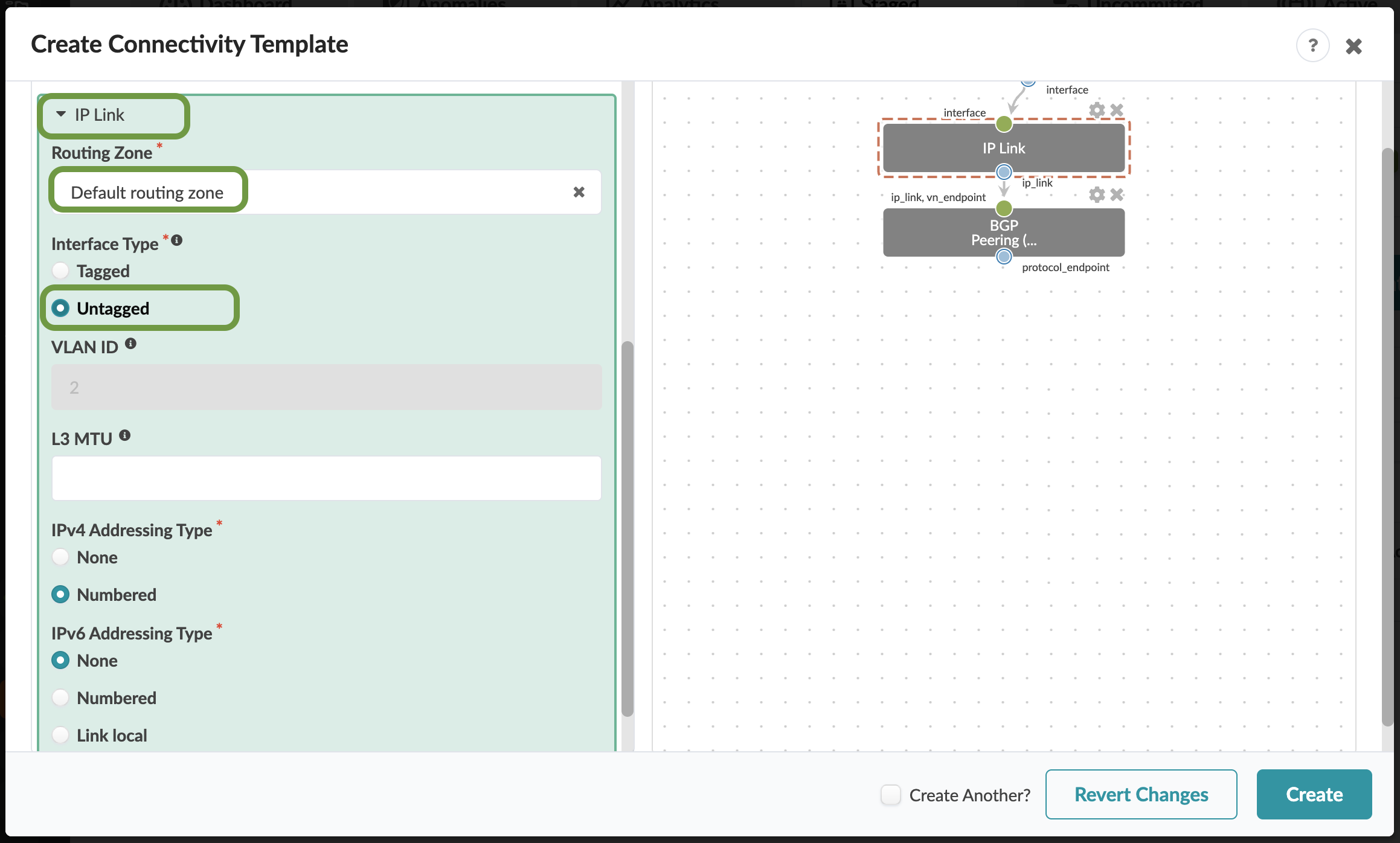
Click the IP Link arrow to edit the parameters with the values shown below.
Table 2. Table IP Link Parameters Property Value IP Link (hover and select the Edit pencil)
IP Link Default (click save icon)
Routing Zone
Default routing zone
Interface Type
Untagged
-
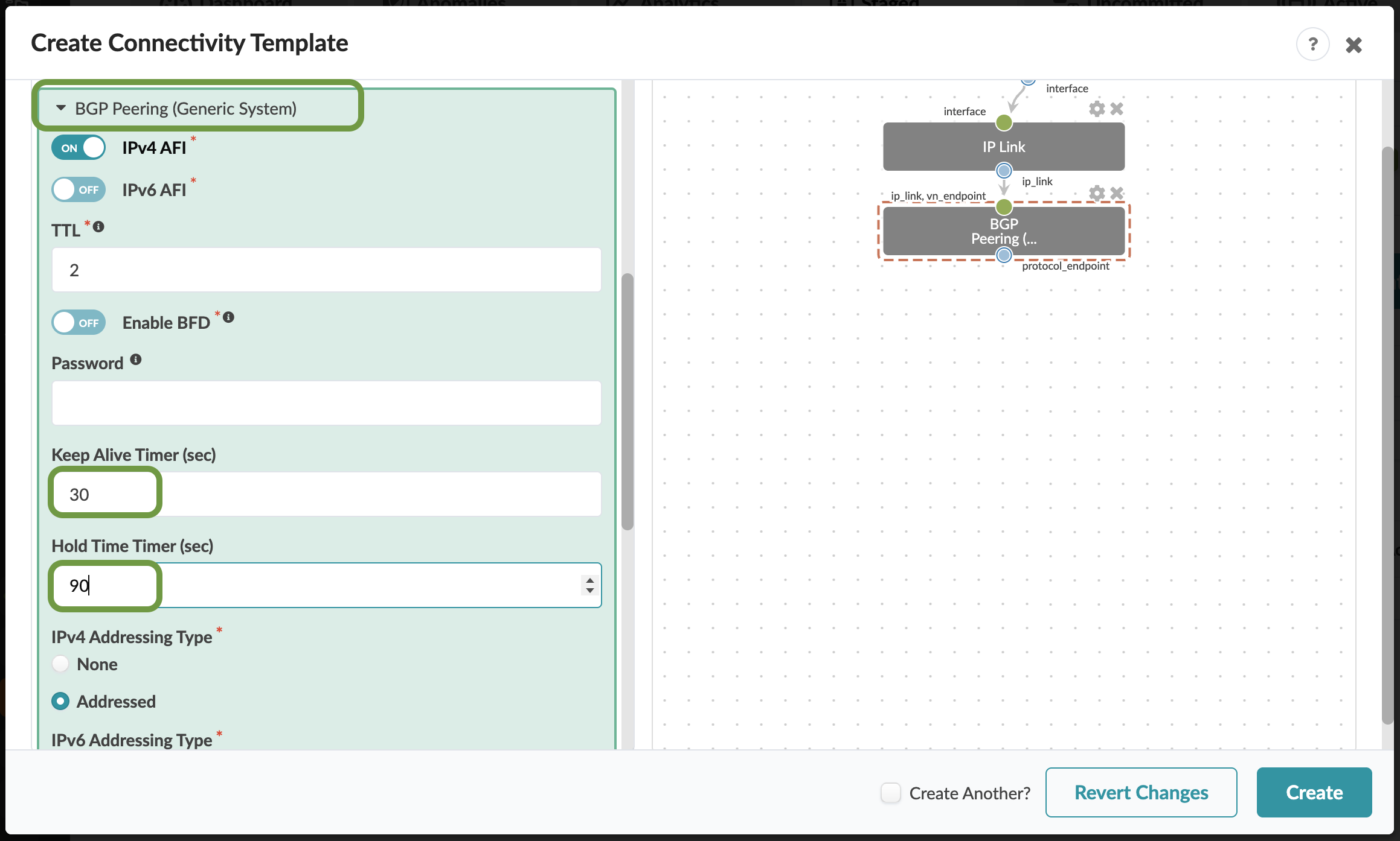
Click the BGP Peering arrow to edit the parameters with the values shown below.
Table 3. Table Configure BGP Peering (Generic System) Parameters Property Value BGP Peering (hover and select the pencil icon to edit the title)
BGP Peering Default (click the Save icon)
Keep Alive Timer (sec)
30
Hold Time Timer (sec)
90
-
Scroll down to see the rest of the settings. The default values are appropriate for our CT.
-
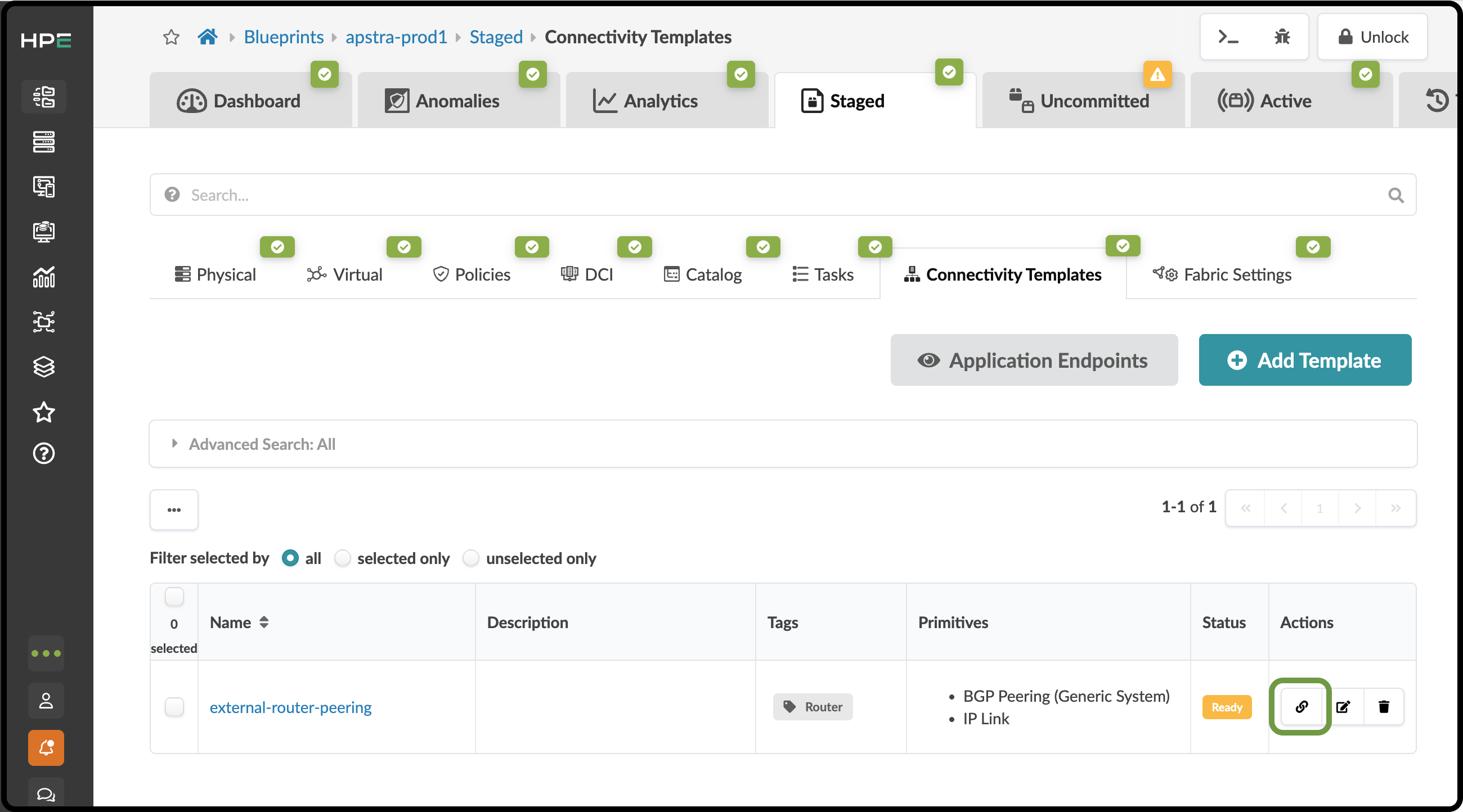
Click Create. If everything is defined properly, the connectivity template is listed and the status column shows Ready. Now, click the Assign icon to open the view where you will associate the CT with the external-router links.
-
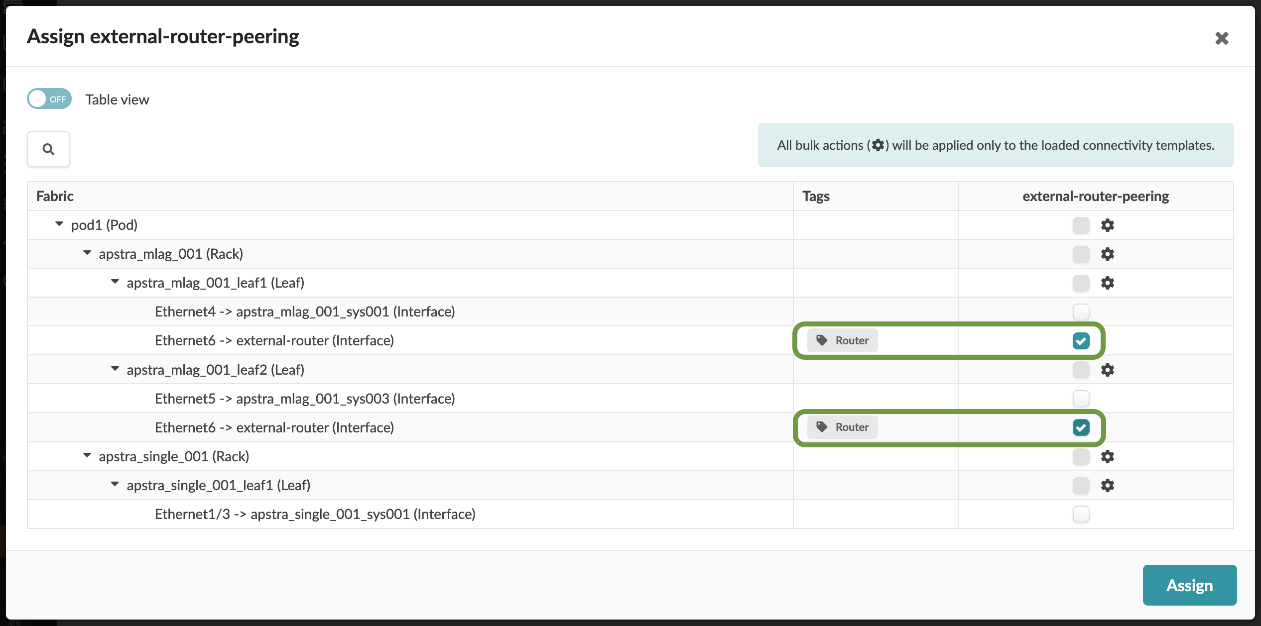
In the Assign external-router-peering window, check the box for each switch interface assigned to the external router. Notice the Router tag next to each of these interfaces. Tags are useful for identifying objects and are used in more depth later. After checking the two boxes, click the Assign button to complete the association with these links.
-
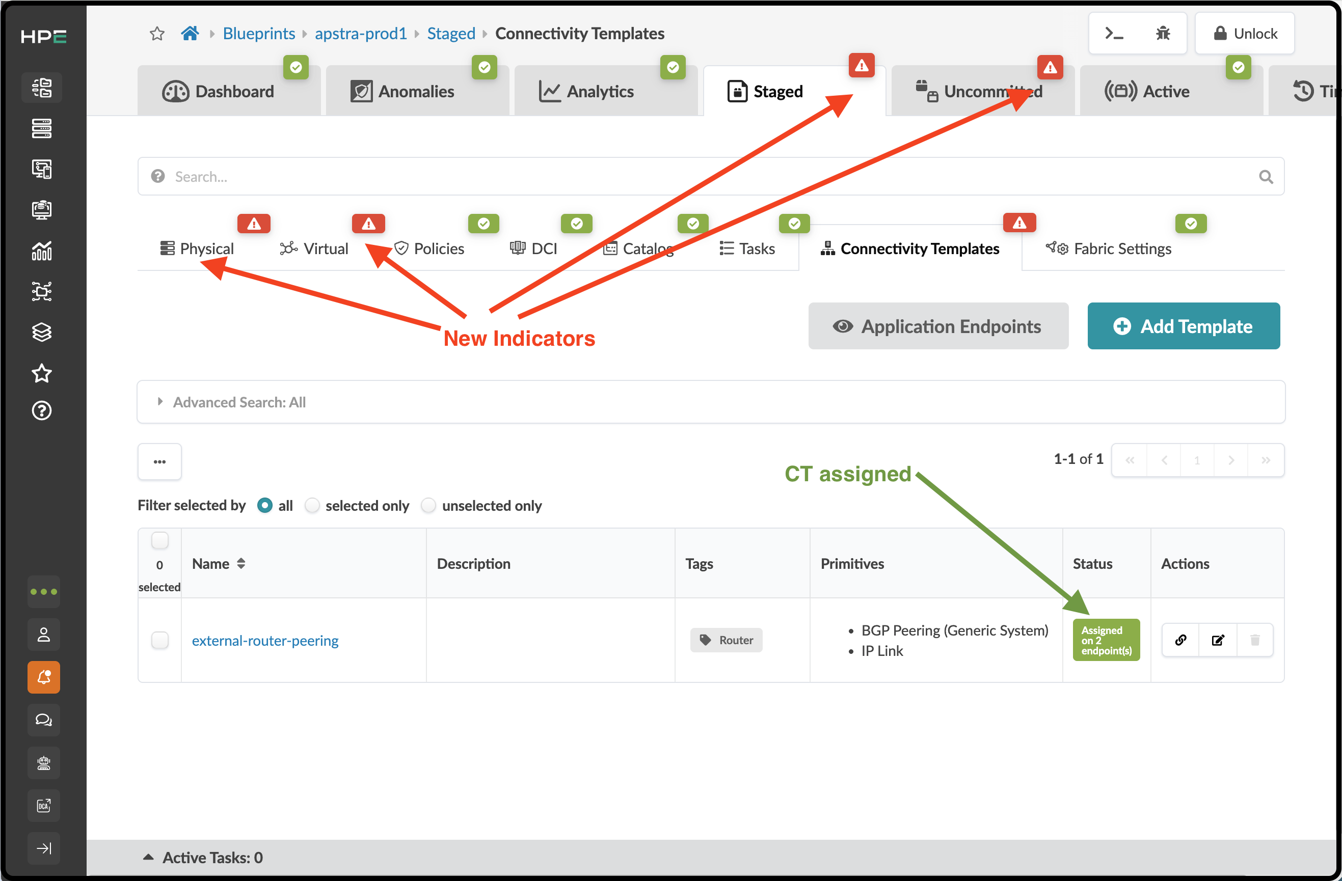
After Assign is clicked, the blueprint view will show new information. First, note that the Connectivity Template shows that it is Assigned on 2 endpoints. Second, there are some new red indicators that we must address.
-
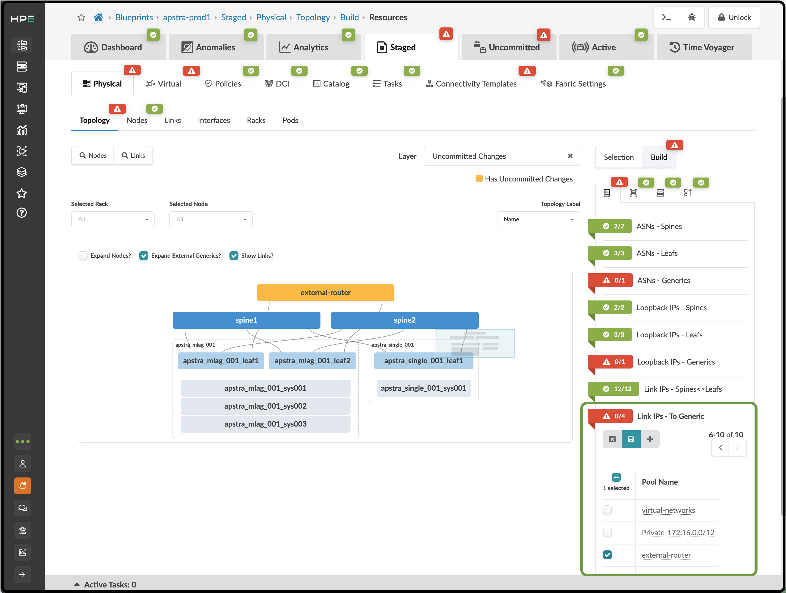
The creation and assignment of our CT to the external router links has caused Apstra to indicate where additional resource assignments are needed. First, navigate to Staged > Physical > Build > Resources. Click Link IPs - To Generic and assign the external-router IP address pool. Once you have selected the IP pool, click the diskette icon to save your selection.
-
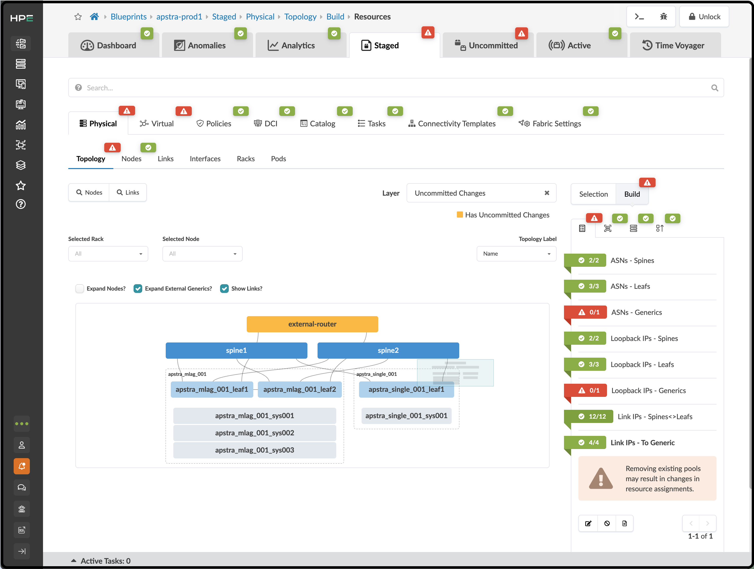
Our blueprint now shows that Link IPs-To Generic is green. However, we still have some red indicators that require our attention.
-
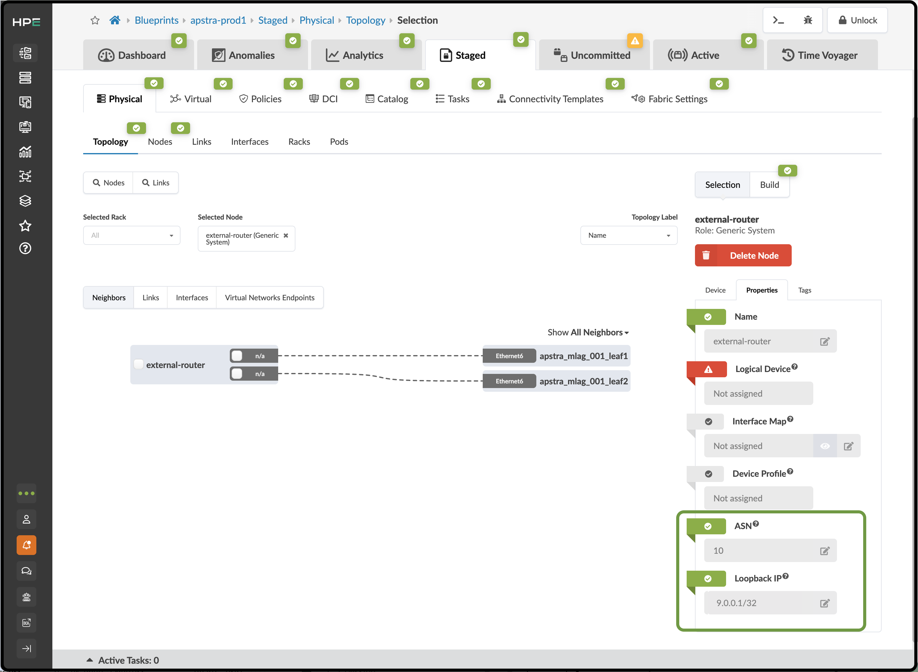
We want to enter specific values for the ASN and loopback because the router VM is already configured. This behavior provides the necessary flexibility to attach an Apstra fabric to existing infrastructure. Click the external-router. You are now in the Selected Node view for this device. On the Build menu on the right, choose the Properties tab. From here, assign the router’s ASN value to 10 (this is the value preconfigured on the ER VM). Next, assign the router’s loopback IP to 9.0.0.1/32. Click the Edit icon for each field and assign the appropriate values. The fields will turn green when the assignments are successful.
-
Click the X to deselect the external router in the Selected Node field. This will move the view up one level.
-
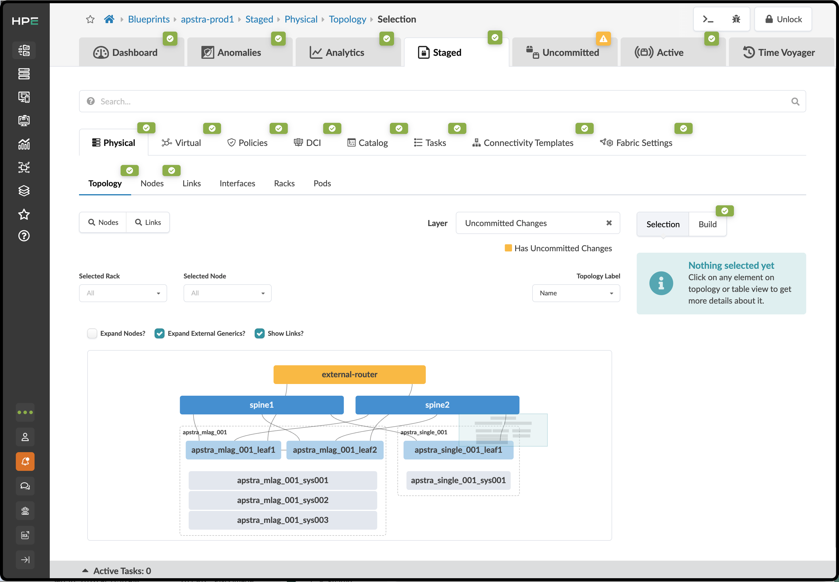
This is how the Staged view of your topology should look at this time. If yours matches this, Apstra has validated that your selections and entries are good, and you can now commit the staged additions to the Active fabric.
Deploy Update to the Blueprint
-
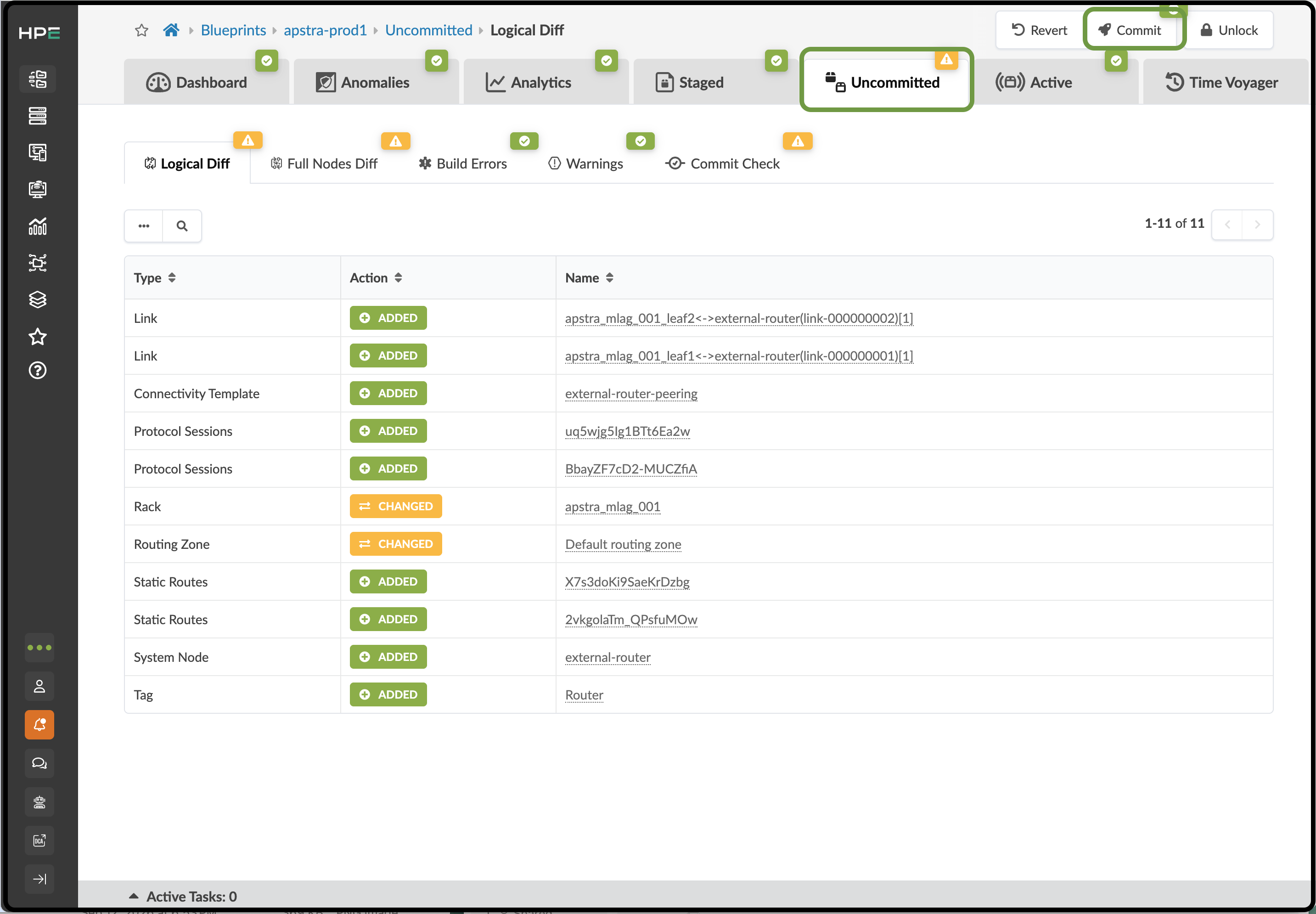
Click the Uncommitted tab to see a summary of the changes you have staged since your first Commit. You created an external router with two links. Then, you applied a Connectivity Template to the links to specify BGP peering from the border leafs. Now, it’s time to deploy these elements to the blueprint.
-
Click the Commit button and enter the description "Milestone 2", then click Commit on the lower right side to push the additions to your blueprint.
-
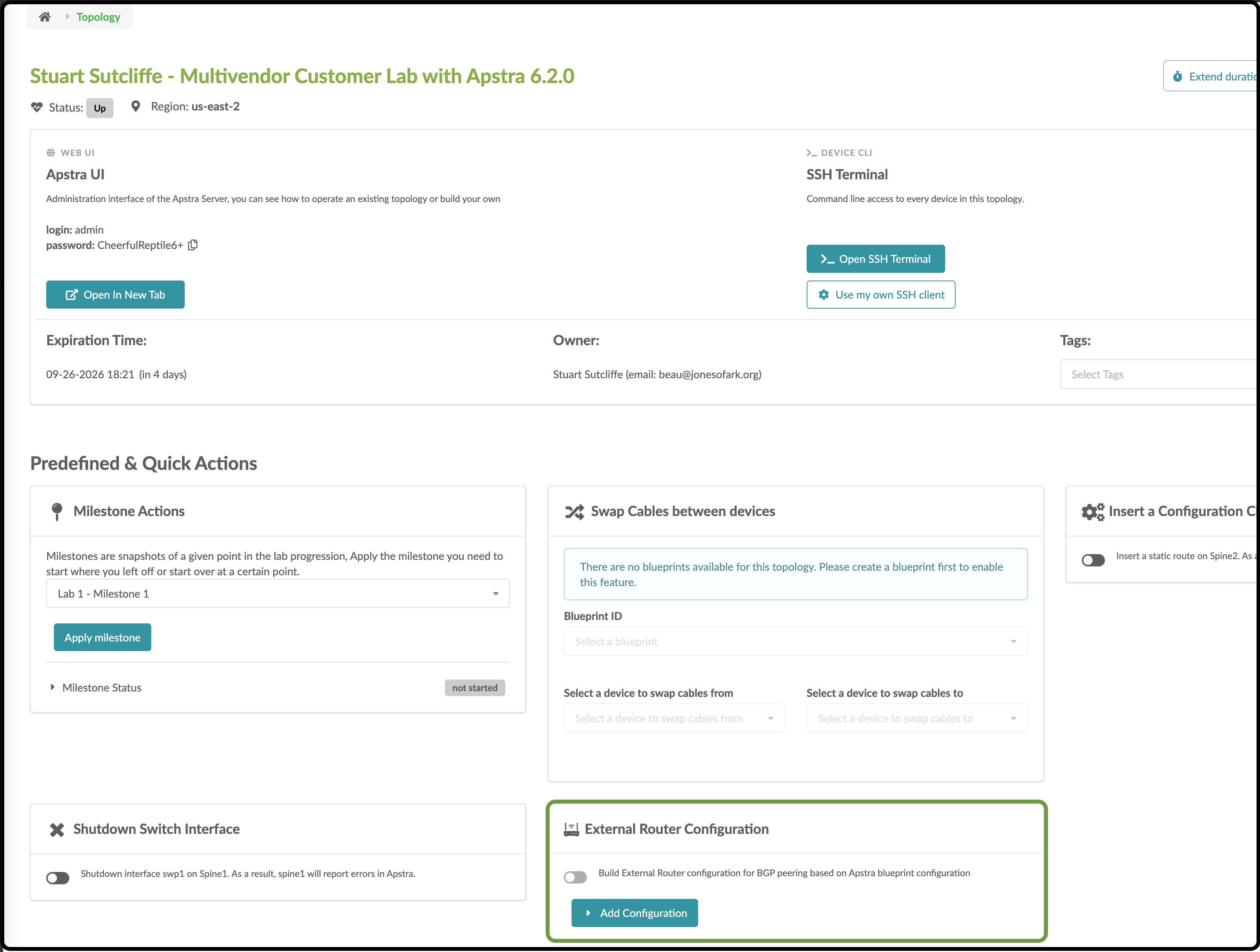
Now, we must perform an additional step for Cloudlabs to update the external router. Apstra doesn’t manage the configuration on this device, so this enables default VRF peering between this router and the leaf pair.
-
Click Add Configuration, enter apstra-pod1 or yourname-pod1 (this value must match what you named your blueprint), and click Submit. The external router will automatically be configured.
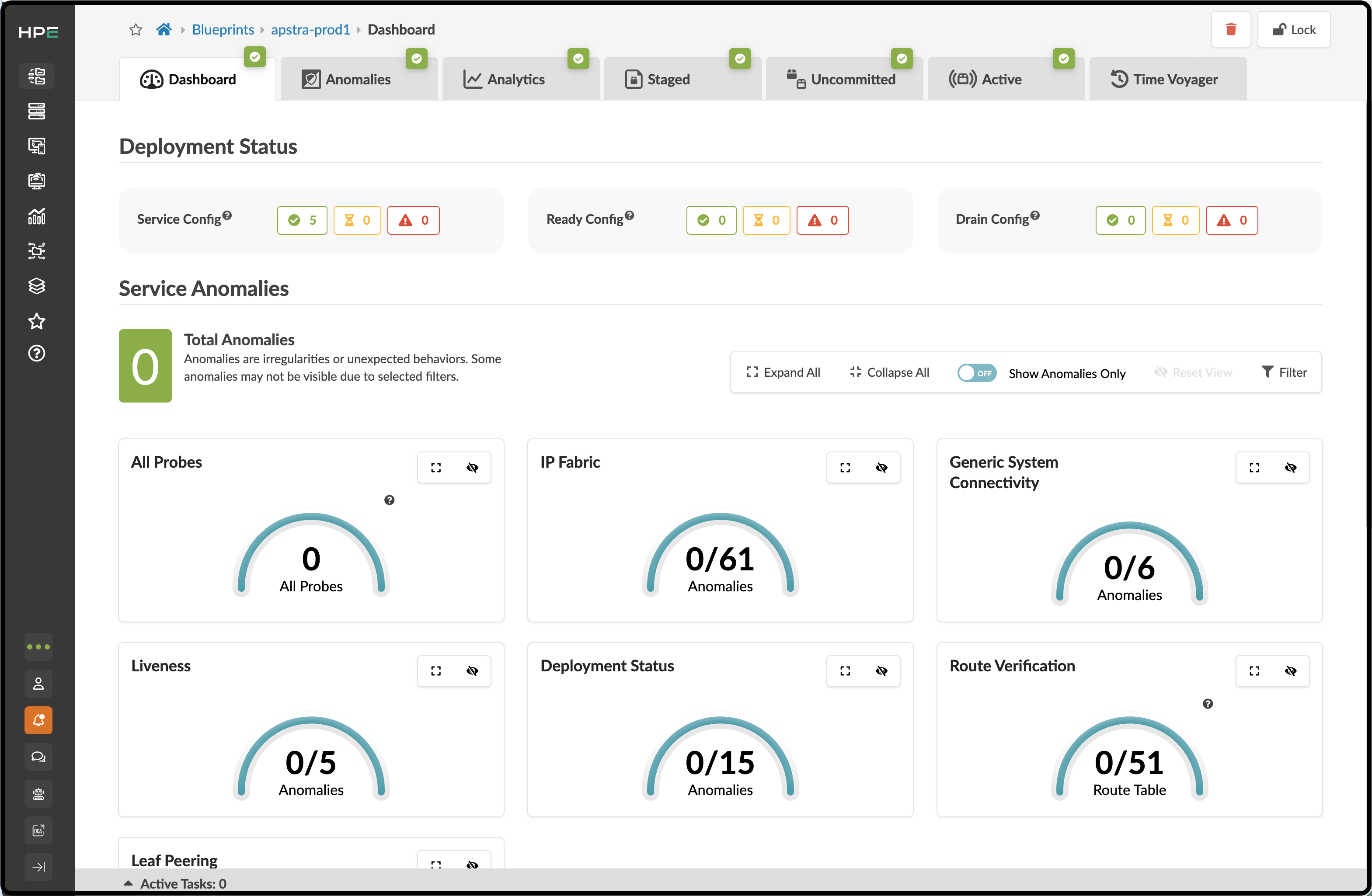
Return to your Apstra server dashboard view. When your screen looks like the one below, you’ve arrived at the second milestone. Congratulations! You’ve successfully deployed and augmented a network with Juniper Apstra!