Lab Guide 1 - Multi-vendor
Blueprints
Now, you will take the elements created in previous sections, along with others that were predefined for you, and bring them together to create a Blueprint. You will then configure individual resources for various elements in the Staged tab. Some elements require resource assignments from pools to complete their configurations. This exercise takes you through the necessary assignments.
As resources are assigned, Apstra automatically allocates what is needed from the specified pools and ensures that all required resources are properly allocated. These details are validated against the design intent before any configurations are applied to the devices. Let’s begin creating the Blueprint.
Create Blueprint
-
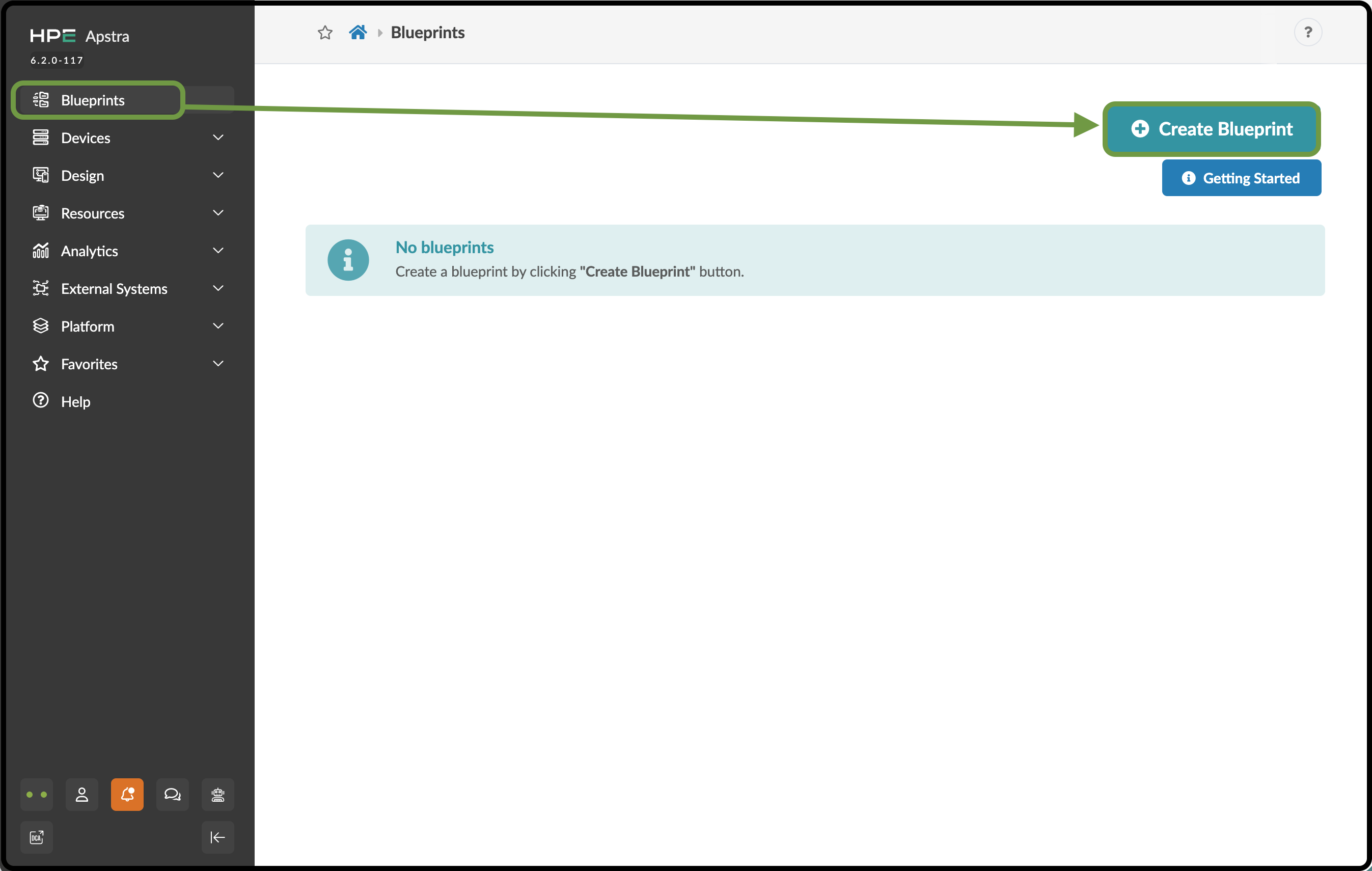
Click Blueprints, then click Create Blueprint.
-
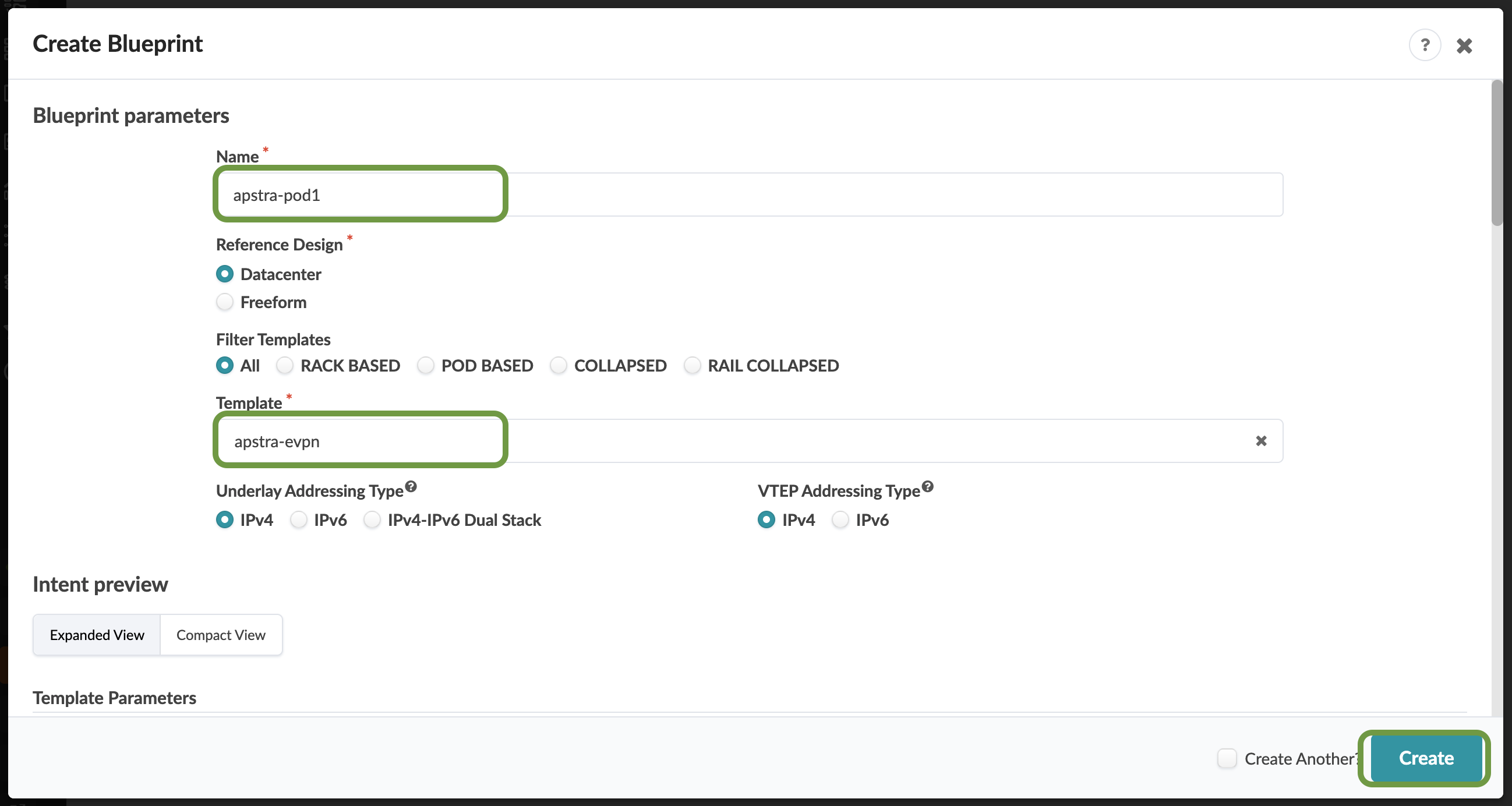
Name the Blueprint apstra-pod1, or replace apstra with your own name if you prefer.
-
From the template drop-down list, select apstra-evpn. A preview of the Blueprint’s intent appears. On this page, match the selections to those shown below.
-
Click Create in the lower-right corner to create the Blueprint and return to the Blueprint summary view. For a moment, you will see Apstra scaffolding the Blueprint.
-
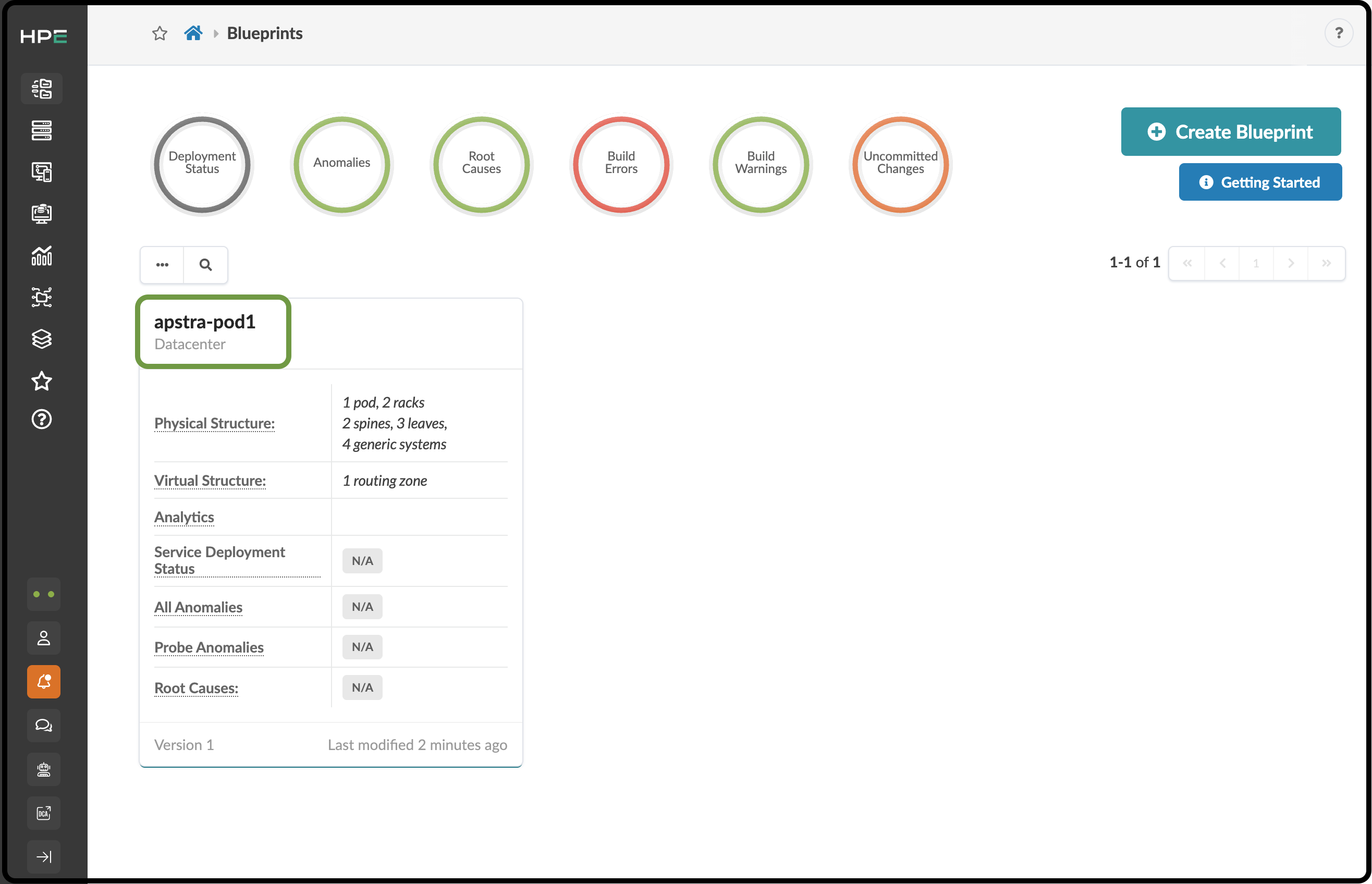
Once complete, click the Blueprint name to open its dashboard. This is where you can check the overall health of the network and quickly see any anomalies. Before we can see information on the dashboard, however, we need to complete the Blueprint build and deploy it. Let’s get started by clicking the Blueprint you just created.
Assign Resources
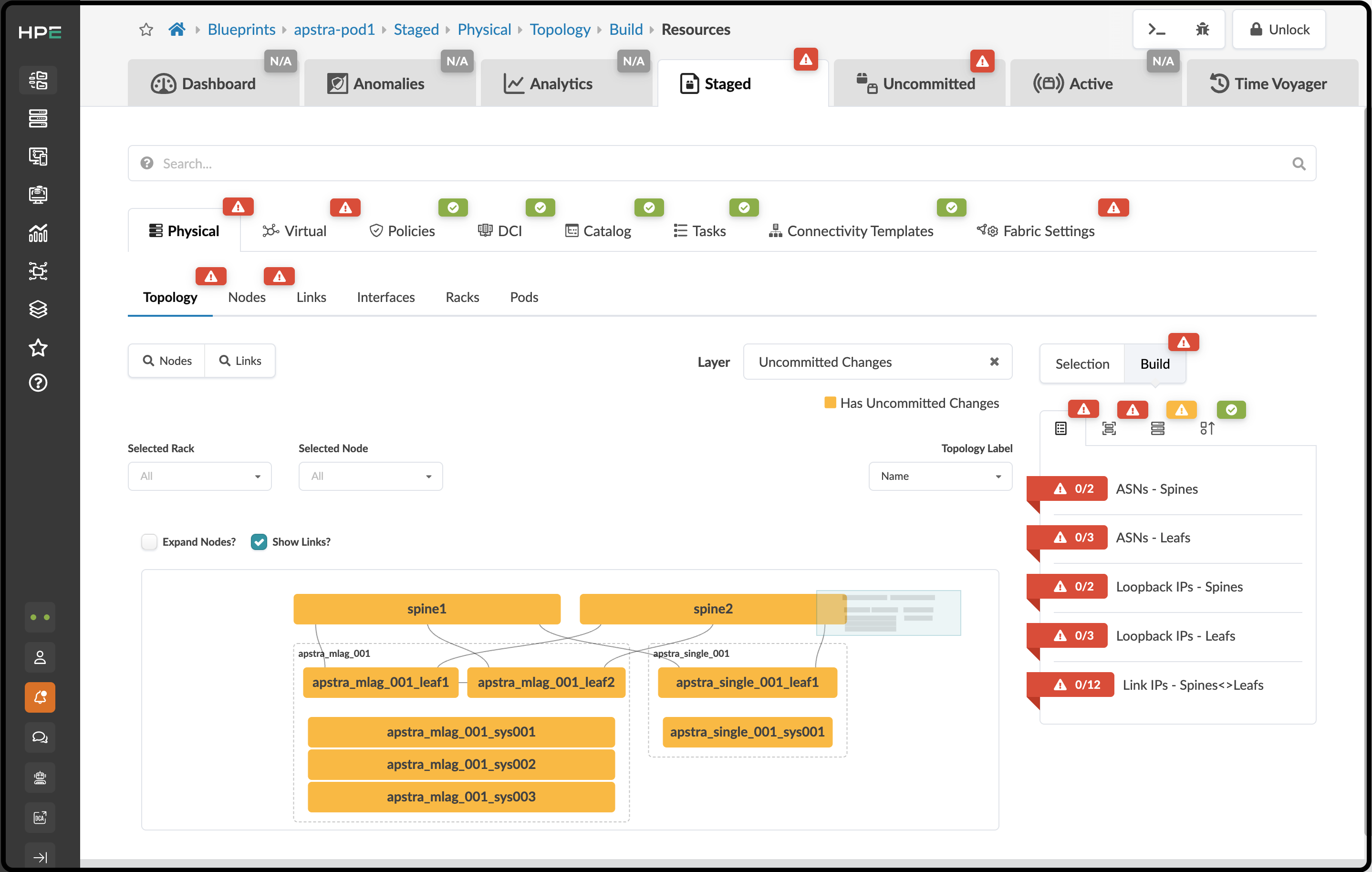
You’ll notice red indicators showing where assignments are needed. These indicate where additional assignments are required to complete the definitions and prepare the Blueprint for deployment. Let’s begin making these assignments.
-
From the Blueprint, navigate to Staged > Physical > Build > Resources.
-
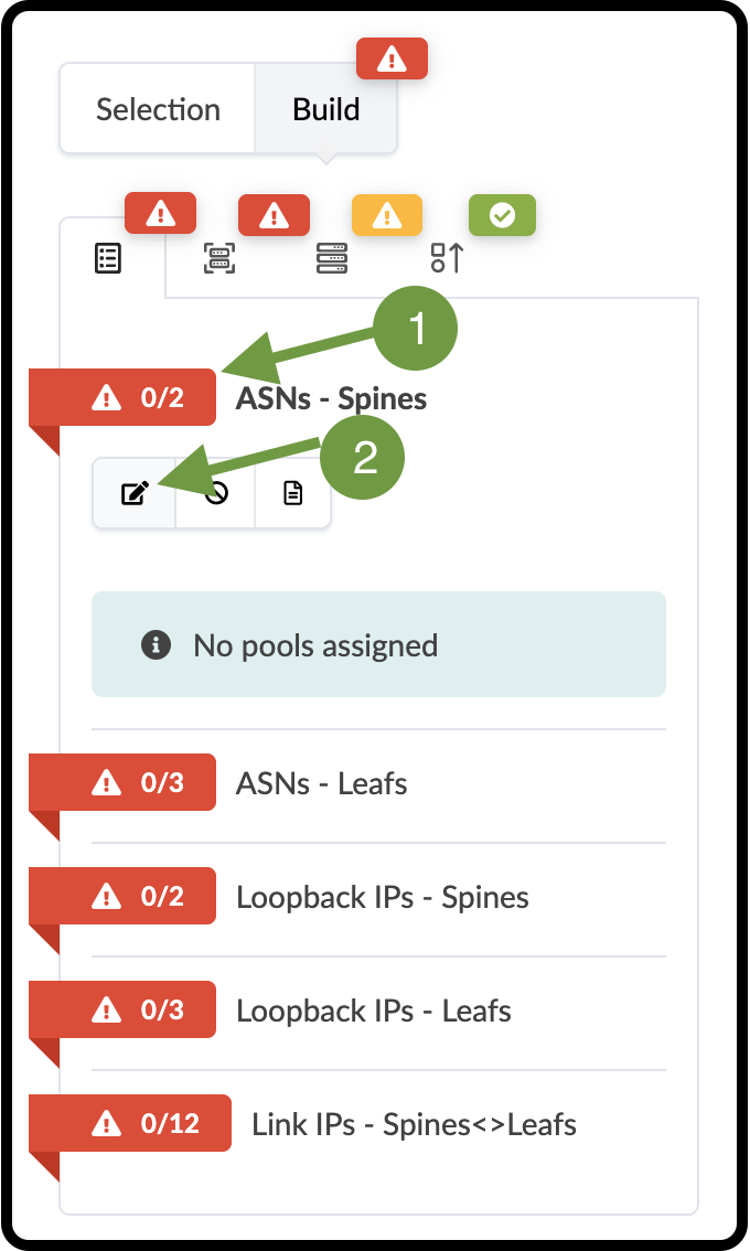
Click the red status indicator next to one of the required resources, then click the Update assignments button to see the available resource pools.
-
Select the pool specified in the table below for the resource you are assigning.
Table 1. Table Pool Resources Resource Requirement Resource Pool ASNs - Spines
vpod-evpn-asn-pool (You created this one.)
ASNs - Leafs
vpod-evpn-asn-pool
Loopback IPs - Spines
spine-loopback (This was created for you.)
Loopback IPs - Leafs
leaf-loopback (This was created for you.)
Link IPs - Spines <> Leafs
spine-leaf (This was created for you.)
If you don’t see the required pool, you may need to click the directional arrow to see additional pools. 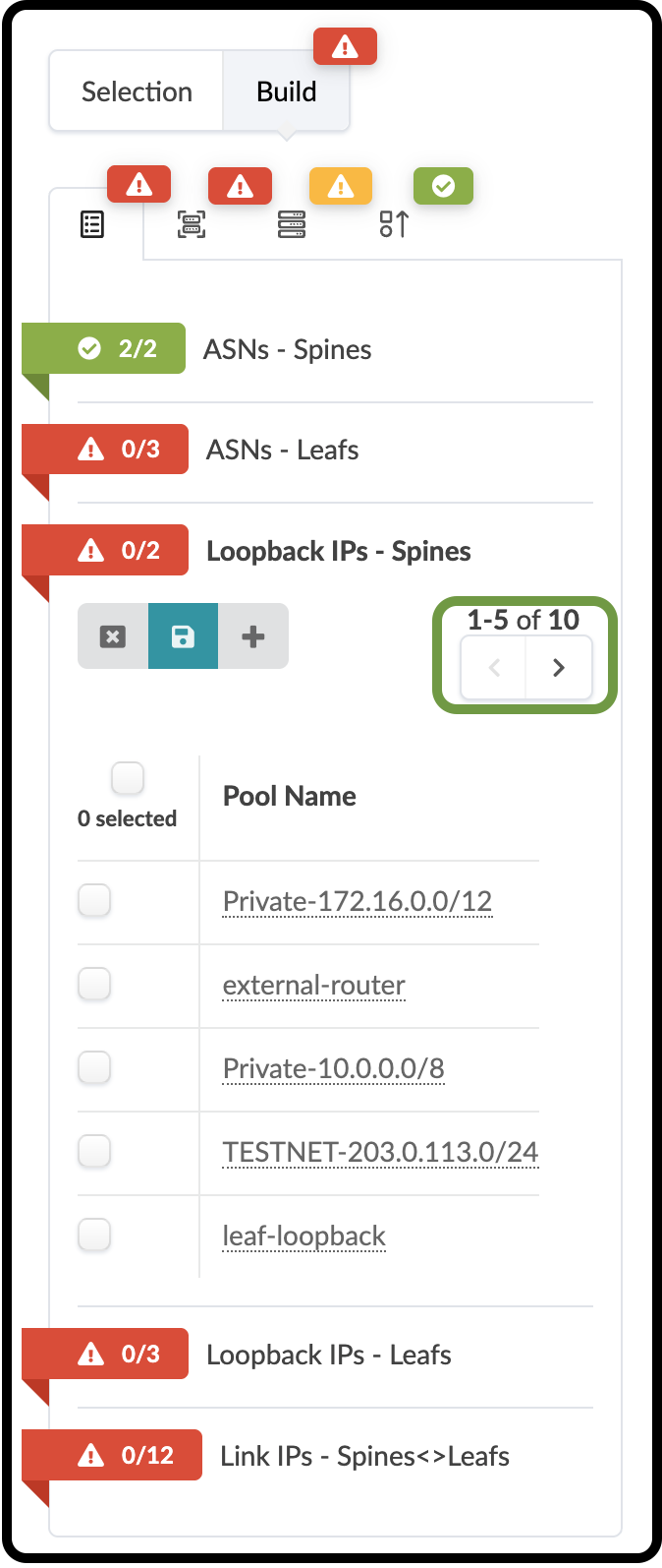
-
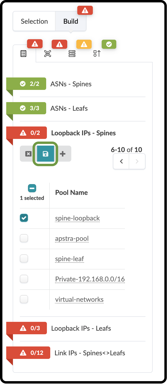
Click the Save button. When the resource has been successfully assigned, the red status indicator turns green.
-
Repeat the steps for each resource requirement.
Assign Devices and Prepare for the First Commit
-
To the right of the Resources tab, select the Device Profiles tab.
-
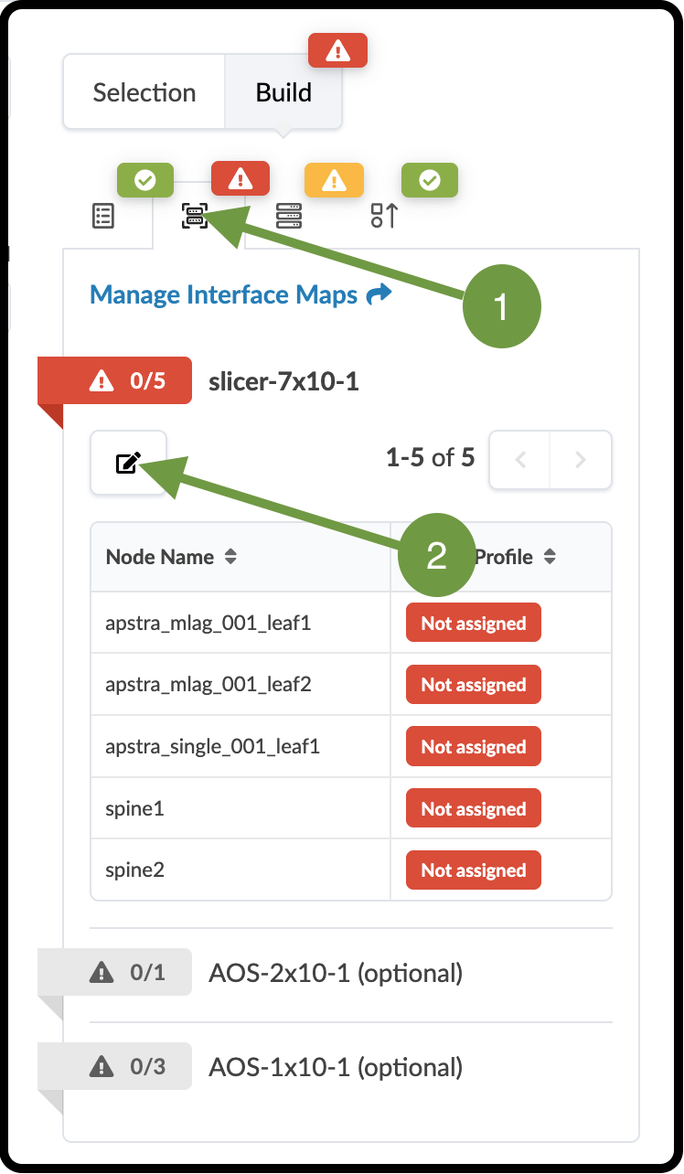
Click the red status indicator next to slicer-7x10⁻¹, then click the Change Interface Maps assignment button.
-
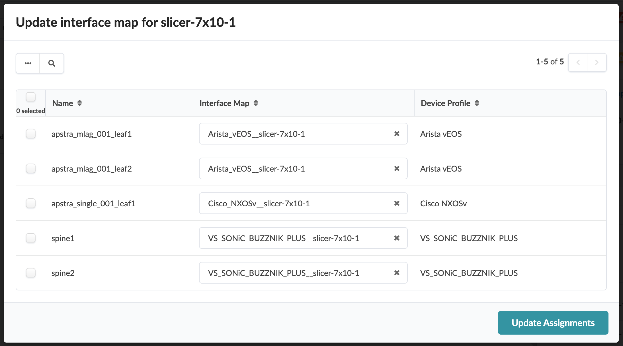
Assign interface maps for each device as shown in the table below.
Table 2. Table Interface Map Assignment Values Name Value apstra_mlag_001_leaf1
Arista_vEOS__slicer-7x10⁻¹
apstra_mlag_001_leaf2
Arista_vEOS__slicer-7x10⁻¹
apstra_single_001_leaf1
Cisco_NXOSv__slicer-7x10⁻¹
spine1
VS_SONiC_BUZZNIK_PLUS__slicer-7x10⁻¹
spine2
VS_SONiC_BUZZNIK_PLUS__slicer-7x10⁻¹
-
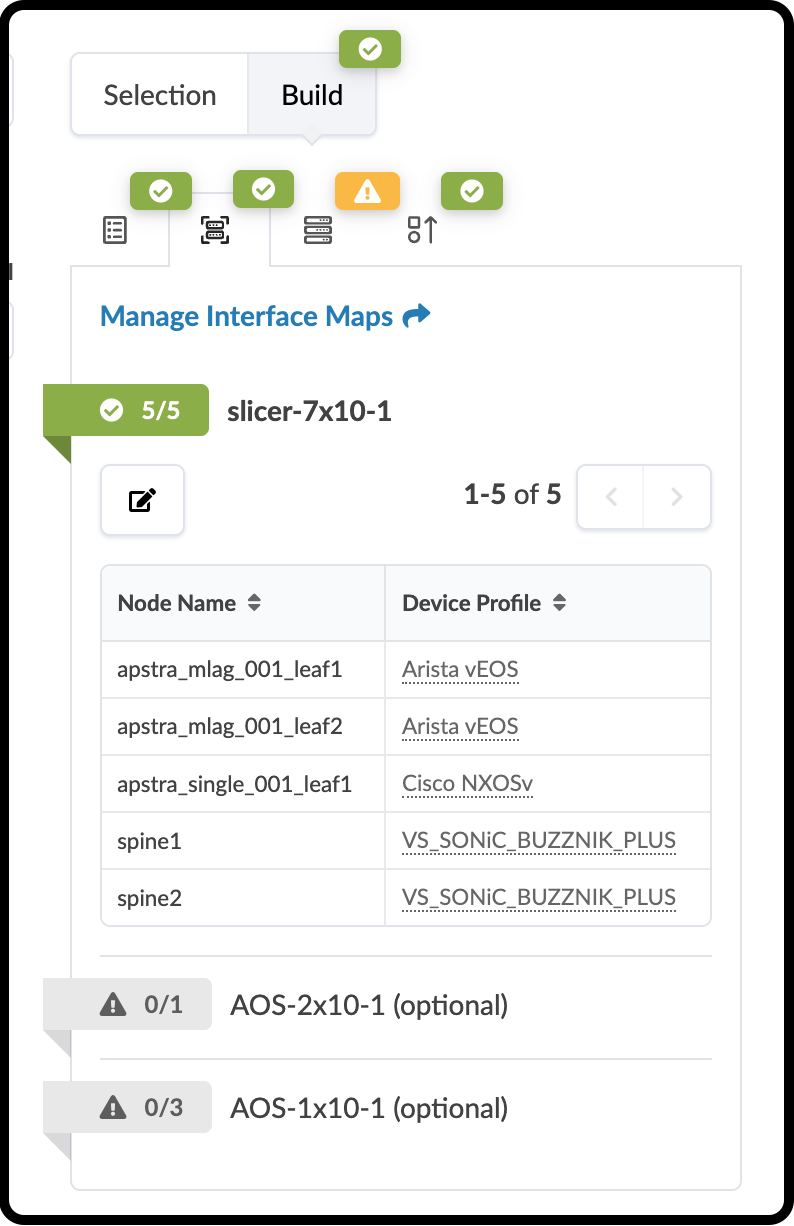
Click Update Assignments to assign the device models and return to the Build page. After a moment, the red status indicator turns green, indicating that the assignments were successful.
Assign System IDs
-
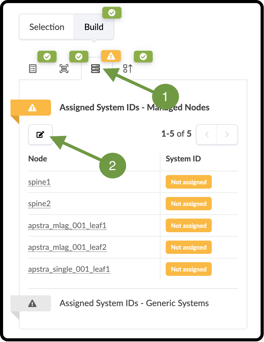
To the right of the Device Profiles tab, select the Devices tab.
-
Click the yellow status indicator next to Assigned System IDs, then click the Change System IDs assignments button.
-
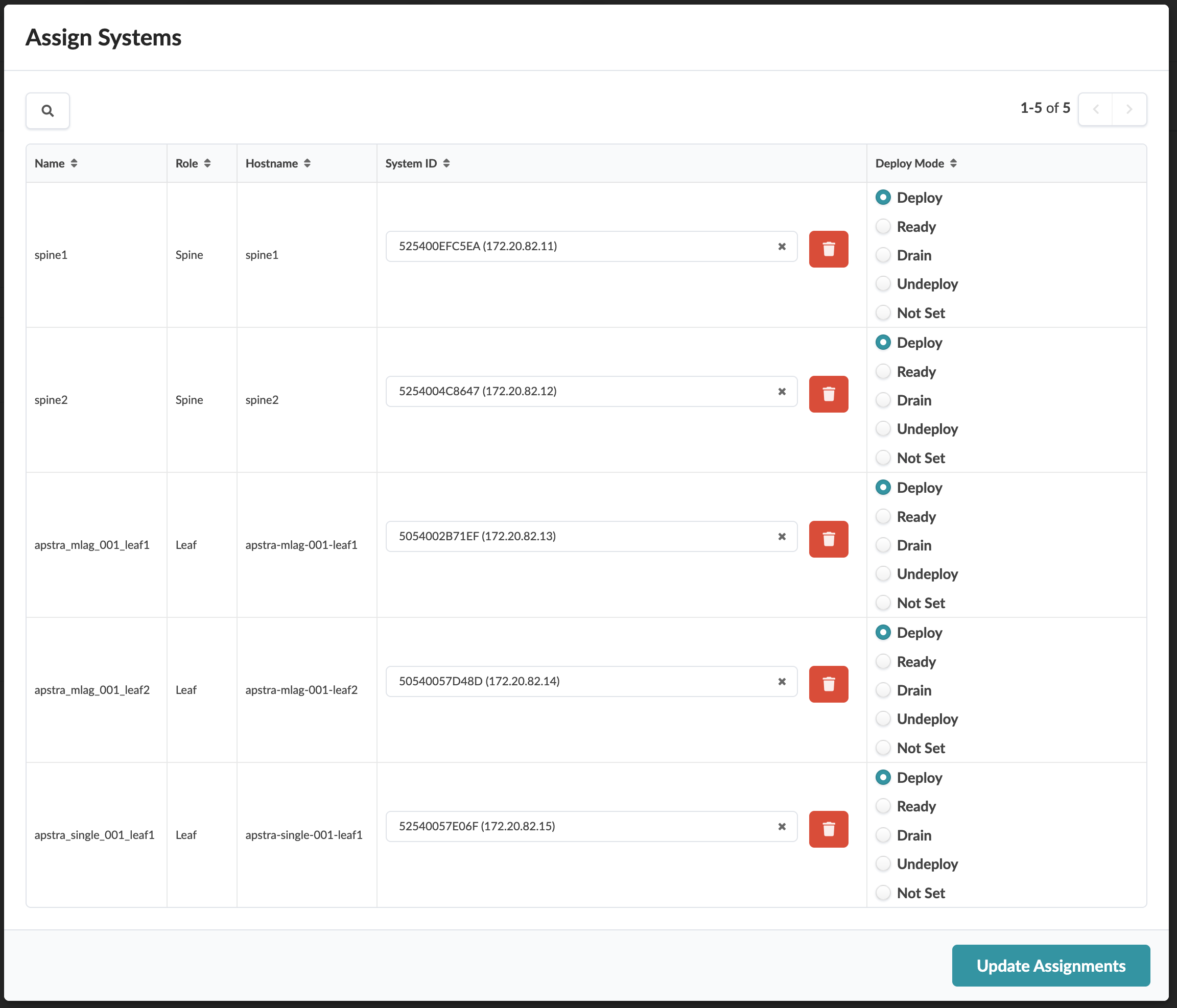
Assign systems as shown in the table below. Note that the subnet of your lab is different from the one shown in the screenshot.
Table 3. Table System ID Values Name Value spine1
172.20.XXX.11
spine2
172.20.XXX.12
leaf1
172.20.XXX.13
leaf2
172.20.XXX.14
leaf3
172.20.XXX.15
-
Assign the devices as shown and ensure that each system is set to Deploy mode. Click Update Assignments to assign the System IDs and return to the Build page. If you have any difficulty making these assignments, make sure you completed the Interface Map assignments correctly in the previous step.
-
At this point, you should notice a new red indicator under Virtual > Virtual Networks. Since the multi-vendor Reference Design uses MLAG for redundancy, which you specified in the Rack Type exercise, an additional resource assignment is required. MLAG requires an IP subnet for the peer links. Let’s assign this resource now.
-
Navigate to Staged > Virtual > Virtual Networks.
-
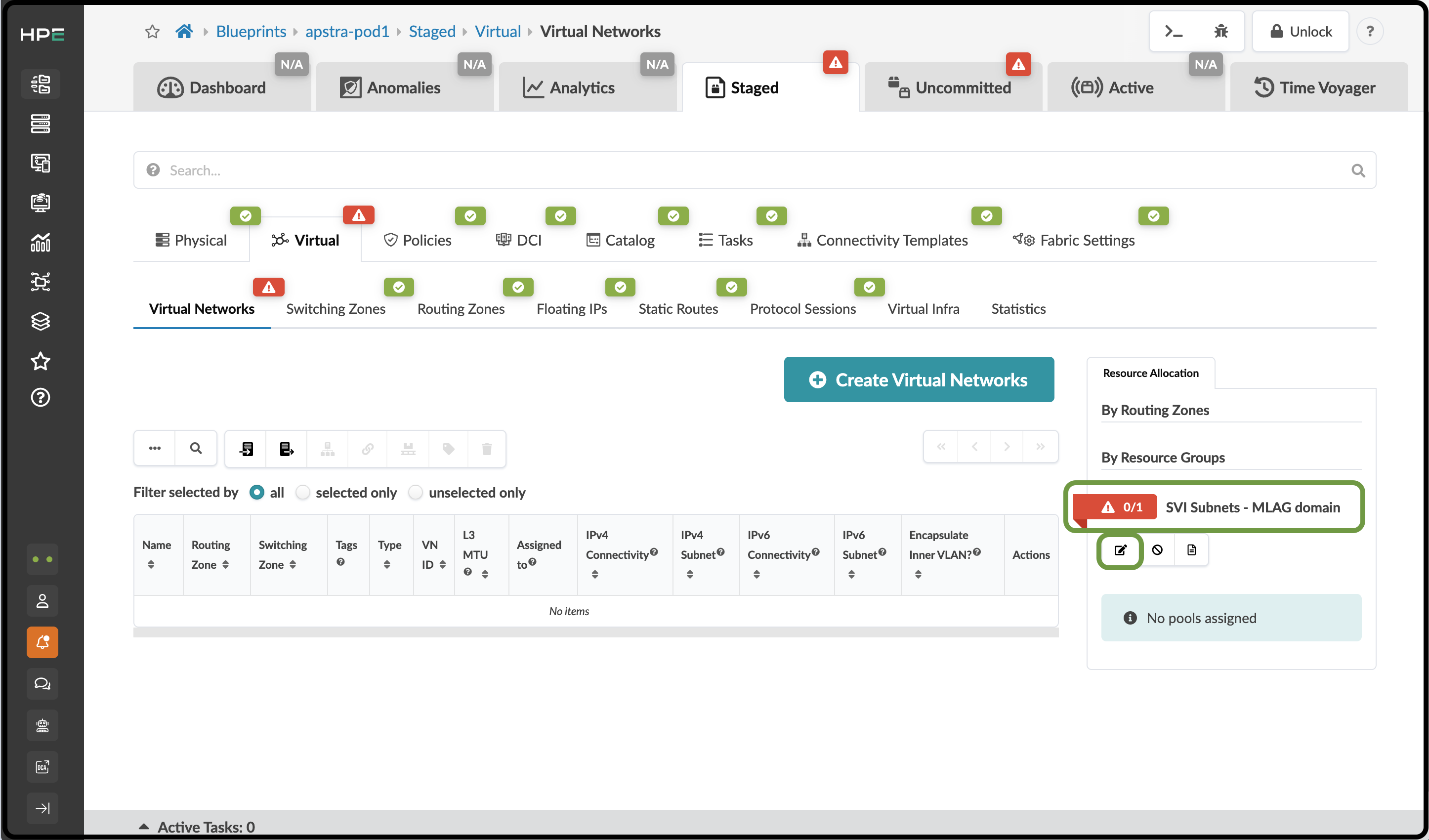
Click the red status indicator next to SVI Subnets - MLAG domain.
-
Click the Update assignments button, then select virtual-networks. You may need to click the directional arrow to see it.
-
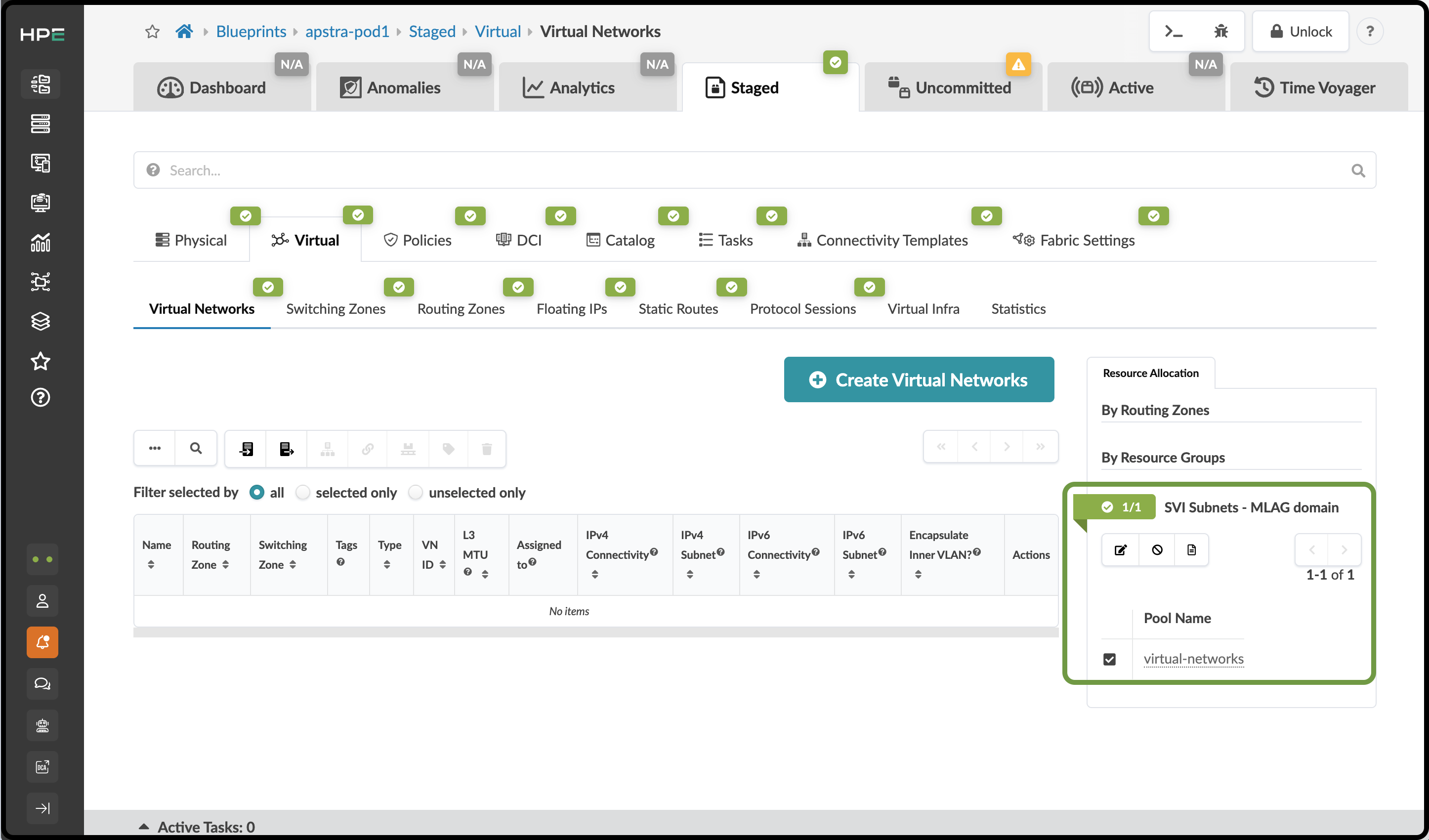
Click the Save button. The red status indicator turns green, indicating that the assignment was successful. You will also notice that the Staged tab is now green, indicating that all resource assignments have been completed.
-
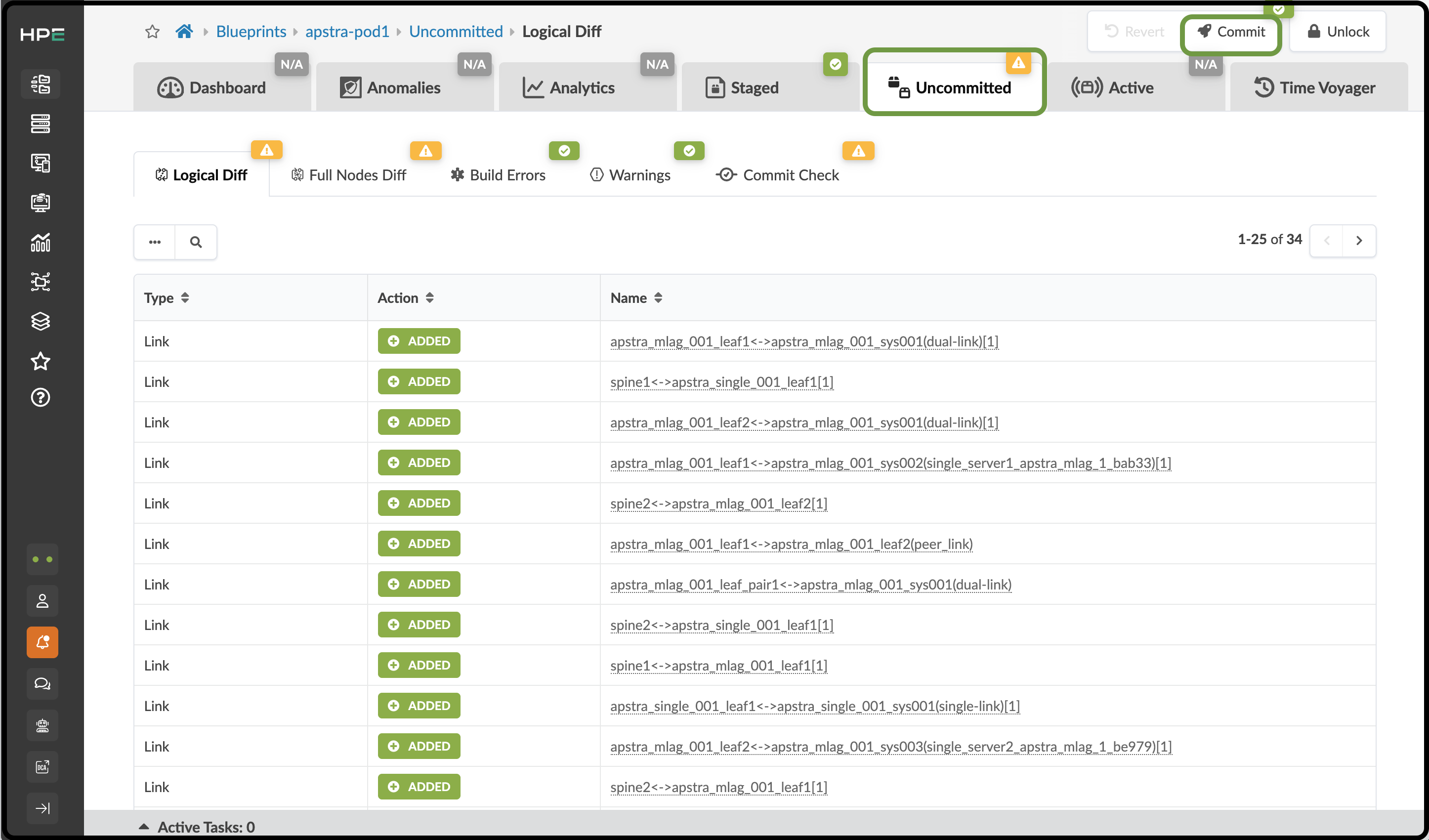
Click the Uncommitted tab. Notice that it is now yellow instead of red. This indicates that all staged changes are ready to be committed to the new fabric.
-
The information displayed represents all changes currently staged for the Blueprint. Because this is the first commit, these are all the changes made since the Blueprint was instantiated from the Template. You can see additional details about the staged changes by clicking the Full Nodes Diff tab. Take a moment to review this screen and become familiar with how changes appear when they are complete and ready to be pushed to the Active network.
-
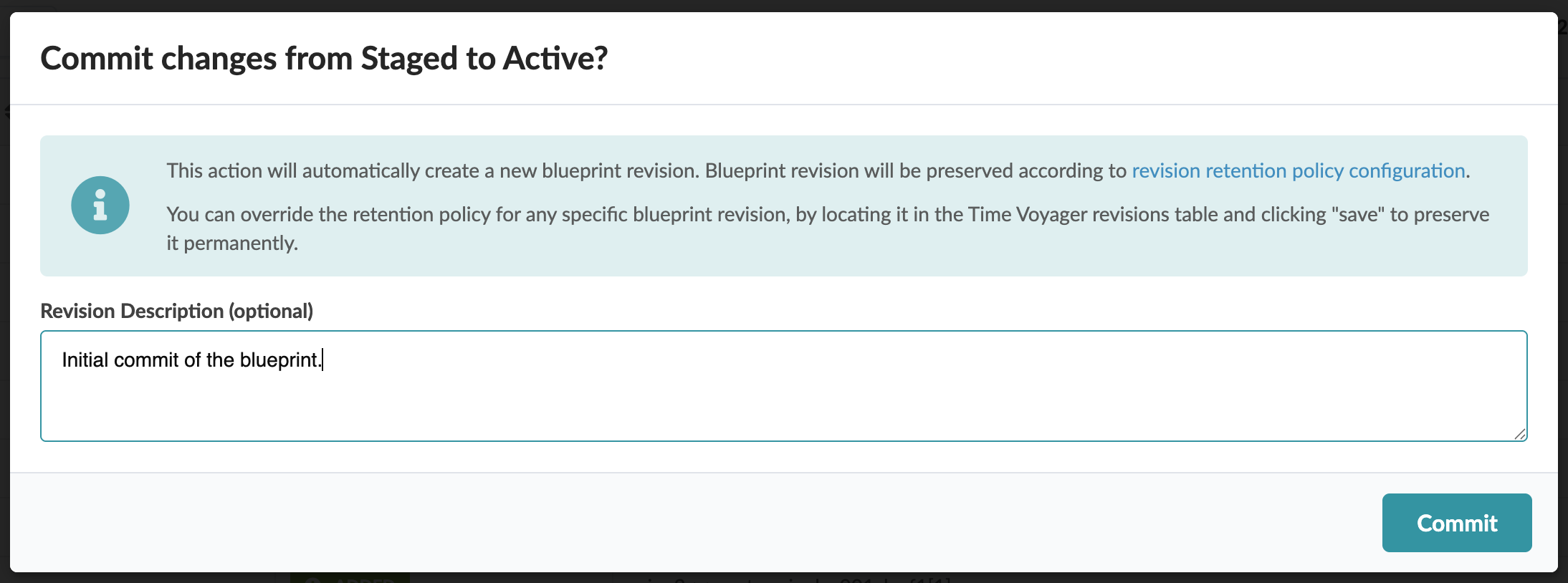
Click Commit to open a screen where you can enter a description of the changes. Enter notes that clearly describe the changes being added to the Blueprint. Descriptive commit messages make it easier to identify fabric snapshots later when using the Time Voyager feature.
-
Once you have entered the description, click Commit and watch as the Active network is configured. This process will take some time. You can open the Active tab to watch the network come to life. The objects will gradually turn green as the agents configure each device and telemetry begins to flow. Once everything is green, you are ready to move to the next exercise.
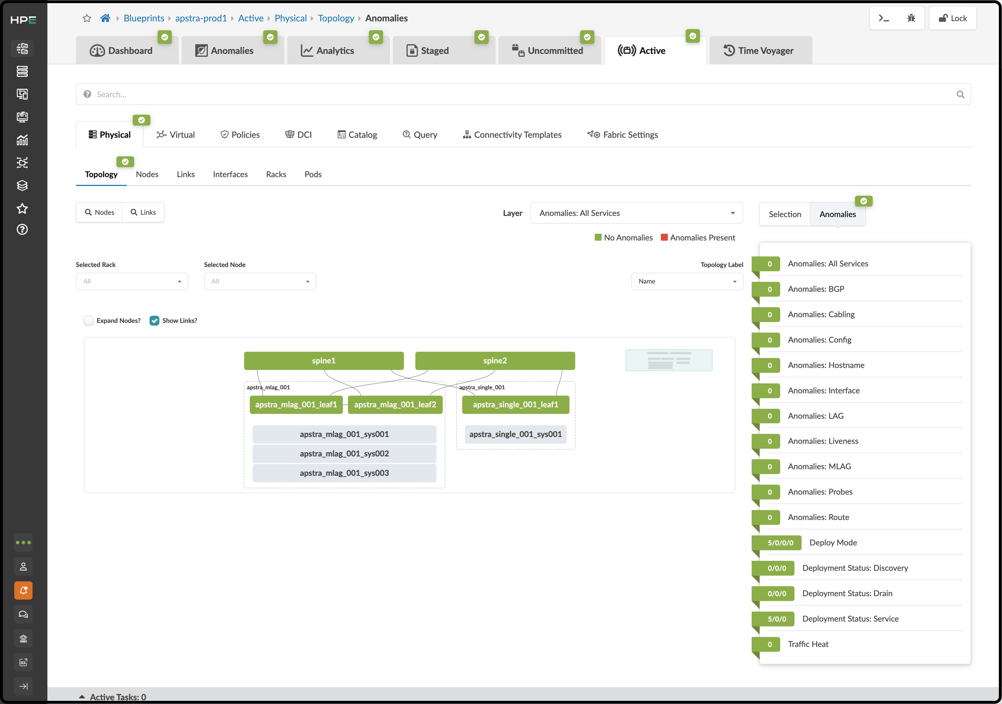
Your network should appear as shown below before moving on to the next exercise, where you will add external connections to your pod.